3 Installation
32551-IMG rev 6
GE Healthcare
25
Fig 3.7.
Attachment of the C-arm
5
Attach the connectors between the carriage and C-arm according to
their numbers (X10, X11, X17, X18, X20, X61).
6
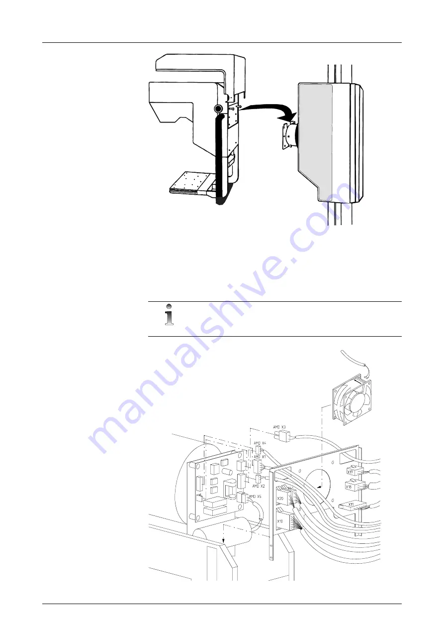
Connectors AMD X1, AMD X2 and AMD X3 are attached to the anode
motor driver (AMD) board inside the C- arm (X61 is only on Alpha RT
models). See Figure 3.8, C-arm connectors.
NOTE!
X20 has 10 wires on the Alpha RT.
Fig 3.8.
C-arm connectors
Summary of Contents for Alpha RT 32551
Page 1: ...GE Healthcare Alpha RT Installation Instructions 32551 IMG rev 6 0459 ...
Page 2: ......
Page 4: ......
Page 42: ...3 Installation 36 GE Healthcare 32551 IMG rev 6 ...
Page 51: ...4 Alpha RT softstart procedure 32551 IMG rev 6 GE Healthcare 45 Fig 4 10 Inverter board ...
Page 52: ...4 Alpha RT softstart procedure 46 GE Healthcare 32551 IMG rev 6 ...
Page 71: ...5 Setups alignments and adjustments 32551 IMG rev 6 GE Healthcare 65 Fig 5 2 Magnetic brake ...
Page 94: ...5 Setups alignments and adjustments 88 GE Healthcare 32551 IMG rev 6 ...
Page 96: ...6 Alpha RT installation step by step 90 GE Healthcare 32551 IMG rev 6 ...
Page 97: ......
Page 98: ......


