g
GE Consumer Service Training
TECHNICAL SERVICE GUIDE
MODEL SERIES:
ADVANTIUM
™
SPEEDCOOKING
GE
Profile Performance
SCA2000BAA
SCA2000BBB
SCA2000BCC
SCA2000BWW
SCA2001BSS
PUB # 31-9038 10/99
TM
Page 1: ...g GE Consumer Service Training TECHNICAL SERVICE GUIDE MODEL SERIES ADVANTIUM SPEEDCOOKING GE Profile Performance SCA2000BAA SCA2000BBB SCA2000BCC SCA2000BWW SCA2001BSS PUB 31 9038 10 99 TM ...
Page 2: ...by individuals possessing adequate backgrounds of electrical electronic and mechanical experience Any attempt to repair a major appliance may result in personal injury and property damage The manufacturer or seller cannot be responsible for the interpretation of this information nor can it assume any liability in connection with its use GE Consumer Service Training Technician Service Guide Copyrig...
Page 3: ...ium Control Panel Features Cooking Guide How to Speedcook Operating Characteristics Index Mechanical Disassembly Index Troubleshooting Index Illustrated Parts Breakdown Six Sigma What is it Last Minute Additions Addendum TABLE OF CONTENTS 58 59 2 4 14 15 16 17 18 22 23 33 45 56 42 43 43 44 TM ...
Page 4: ...od Also be sure to consult the front of the cookbook for proper cookware selection and food placement on the turntable TM Pub No 28 X139 Cookbook The cookbook includes numerous recipes help ful cooking tips information on proper cooking techniques and proper use of cookware for vari ous types of recipes The cookbook is also a helpful diagnostic tool when servicing an Advantium oven for a cooking i...
Page 5: ...view 17 Speedcook cookware 17 Speedcook safe cookware 5 Storing custom speedcook recipes 18 19 Things that are normal 20 Using a pre set speedcook menu 14 Microwaving 22 31 Cooking tips 23 Custom microwave recipe log 31 Defrost auto 26 Defrost time 26 Defrosting tips 27 Micro Express 23 Microwave power levels 23 Microwave safe cookware 6 Precautions to avoid possible exposure to microwave energy 2...
Page 6: ...ical codes The wall outlet receptacle recommended for this appliance is NEMA 14 30R and accepts the four prong grounded plug of this appliance see Fig 1 above IMPORTANT PLEASE READ CAREFULLY FOR PERSONAL SAFETY THIS APPLIANCE MUST BE PROPERLY GROUNDED TO AVOID SEVERE OR FATAL SHOCK DO NOT UNDER ANY CIRCUMSTANCES CUT DEFORM OR REMOVE ANY OF THE PRONGS FROM THE POWER CORD DO NOT USE WITH AN EXTENSIO...
Page 7: ...ed down far enough to keep the oven level Keep the space between the bottom of the cabinet and the mounting plate equal to the height of the top front trim This will insure level installation of the oven PARTS INCLUDED You will find the installation hardware packed with the unit Check to make sure you have all these parts The installation hardware 1 7 should include the following Hardware List Qty...
Page 8: ...tal duct length of 31 4 x 10 rectangular or 6 diameter round duct should not exceed 140 equivalent feet ELBOWS TRANSITIONS WALL AND ROOF CAPS etc present additional resistance to airflow and are equivalent to a section of straight duct which is longer than their actual physical size When calculating the total duct length add the equivalent lengths of all transitions and adaptors plus the length of...
Page 9: ...ly 1 Remove and discard the 2 screws for the blower plate 2 Position the exhaust adaptor hardware item 5 over the blower plate hinge side toward the back of the oven 3 Attach the exhaust adaptor to the blower plate using the 2 bronze metal screws provided hardware item 6 4 Proceed to the PREPARATION OF TOP CABINET section For flat bottomed cabinets proceed to the PREPARATION OF TOP CABINET section...
Page 10: ...he screws that hold the blower plate to the oven 2 Slide the blower plate back from under its retaining flange and lift it off Remove and save the screw that holds the blower motor to the oven 3 Carefully pull out the blower unit The wires will extend far enough to allow you to adjust the blower unit Turn the blower unit end over end Reroute the wires through the grooves on the other side Roll the...
Page 11: ...e them for possible future use You must use the Charcoal Filter Kit See your Owner s Manual for kit number 1 Remove and save the screws that hold the blower plate to the oven 2 Slide the blower plate back from under its retaining flange and lift it off Remove and save the screw that holds the blower motor to the oven 3 Carefully pull out the blower unit The wires will extend far enough to allow yo...
Page 12: ...les following the instructions on the template 6 ATTACH THE MOUNTING PLATE TO THE WALL Your oven needs to be mounted against and supported by a flat vertical wall Wall construction should be a minimum of 2 x 4 wall studding and 3 8 or more thick drywall or plaster lath The oven must be attached to a minimum of one 2 x 4 wall stud 1 Find the studs using one of the following methods A Stud finder a ...
Page 13: ... toggle wings to 3 4 past the bolt ends Insert the toggle wings into the holes in the wall to mount the bracket You may pull forward on the bracket to help in tightening the toggle bolts Tighten all bolts For outside back exhaust The oven requires a rear wall cutout opening for the rear wall duct and the exhaust adaptor must be attached to the mounting plate See the next page on how to prepare the...
Page 14: ...allation Return to step 7 item 5 page 9 to continue After completing the installation of the mounting plate again check the rear damper for free movement to assure it will operate properly F I H G MOUNT THE OVEN FOR EASIER INSTALLATION AND PERSONAL SAFETY WE RECOMMEND THAT TWO PEOPLE INSTALL THIS OVEN IMPORTANT Do not grip or use handle during installation 1 Locate the grease filters packed separa...
Page 15: ...dia to fit the screws you purchase This will prevent the screw heads from pulling through the bottom of the cabinet when tightening during installation 4 Install the grease filters and remove the tape from the cooktop lamp covers on the bottom of the oven 5 Secure the power cord to the cabinet wall as desired to keep excess length out of the way Use the power cord strap hardware item 7 and the bla...
Page 16: ... 13 19 32 Overall Dimensions Exterior Height front 15 19 32 Exterior Height rear 16 3 32 Exterior Width 29 7 8 Exterior Depth not including handle 14 13 16 Power Ratings Amps 240V 208V 30 Warranty Full One year In Home Warranty Full Ten year Lamp Warranty Limited Ten year Magnetron Warranty See written warranty for details Six o clock What s for dinner How about a delicious family meal cooked in a...
Page 17: ...other than the intended purpose or used commercially Replacement of house fuses or resetting of circuit breakers Damage to the product caused by accident fire floods or acts of God Incidental or consequential damage to personal property caused by possible defects with this appliance This warranty is extended to the original purchaser and any succeeding owner for products purchased for home use wit...
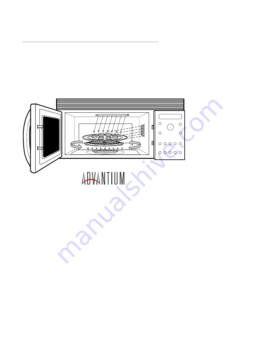
Page 18: ...s directed through the wave guide into the oven cavity Oven turntable The turntable rotates the food during speed cook operation and during microwave operation The rotation of food serves to evenly distribute the microwave energy and halogen heat 1 2 3 4 Black Metal Tray Baking Sheet Used during speedcooking only Put food directly on the black metal tray and place on the oven rack turntable when u...
Page 19: ...onds of microwave cooking each time you press it Oven starts immediately MICRO WAVE HELP MICROWAVE OVEN LIGHT Press to active the selector dial to microwave mode Press during microwave cook ing to light the oven cavity top rear halogen lamp on for approximately 3 seconds CLEAR OFF Cancels all oven programs except clock timer reminder and delay start Child lockout hold for 3 secs to lock or to unlo...
Page 20: ...ny time even when the oven is operating It can be set to beep at a certain time up to 24 hours later O P T I O N S Press this button to set the Clock and access the Auto Night Light Beeper Volume Clock Display ON OFF Display Scroll Speed features H E L P Press this button to find out more about your oven s features S U R F A C E L I G H T Press this button to turn the cooktop light on and off Cook...
Page 21: ... Potatoes Frozen French Fries Crinkle Fries Coated Fries Regular Fries Steak Fries Waffle Fries Frozen Tater Tots Pierce skin with fork in several places Select appropriate size for best cooking results For crisper texture increase time in 15 second increments Follow pkg directions for serving size Ore Ida Kroger Burritos froz Corn Dogs Crescent Roll Hot Dogs Grilled Sandwiches Pocket Sandwiches F...
Page 22: ...on Turn the dial until Recipe appears Press to enter Follow the directions on the control For more detailed information refer to your Owner s Manual U S I N G T H E O V E N Place the oven rack turntable on the floor of the oven for all cooking procedures When cooking with the speedcook feature place casseroles and baking dishes directly on the oven rack turntable The black metal tray is placed on ...
Page 23: ...ks Broil Turn fish over after half time Reduce time for 1 inch 12 18 min U 10 L 10 M 05 8 min thinner steaks add time for thicker steaks Fillets 8 9 min U 10 L 10 M 00 7 min Brush black metal tray lightly with oil to prevent sticking Lamb Chops 6 Broil U 10 L 10 M 00 1 inch medium 8 10 min 8 min Turn over during last 2 to 3 minutes 1 1 2 inch medium 11 13 min 10 min Turn over during last 2 to 3 mi...
Page 24: ...he Advantium 4 ADJUST TIME or START appears Press Start or selec tor dial to begin cooking 5 Once the oven starts cooking you will see your selection in the display with remaining cooking time counting down 6 After approximately 3 5 secs the cook time may be adjusted up or down to compensate for variations in line voltage 7 Minutes before cooking ends CHECK for DONENESS appears Power shuts off unt...
Page 25: ...Balance Thermal Compensation Thermal Protection Thermal Safety Damper Door Assembly Damper Door Sensing Switch Oven Cavity Lamp Thermal Fuse Air Flow Vent Motor Halogen Blowers Upper Lower Magnetron Blower OPERATING CHARACTERISTICS 30 32 24 25 25 25 27 28 28 28 29 29 30 30 ...
Page 26: ...h 32 second period and the microwave high voltage circuit would be energized for 30 of each 32 second period Example Example Example Example Example upper element set at 80 U 08 lower element set at 50 L 05 and microwave set at 30 M 03 Upper Halogen Lamp Pair U The upper halogen lamps provide radiant heat to the top surface of the food Select a higher setting for thin foods requiring a golden brow...
Page 27: ... halogen lamp pair operate together at the same power level How ever in order to provide even balanced cook ing performance the upper rear halogen lamp will always cycle at 85 of the upper front halo gen lamp In other words if the upper halogen lamps are set at power level 10 U 10 you would expect both elements to operate at 100 of each 32 second duty cycle Instead the upper rear halogen will cycl...
Page 28: ...rt board will adjust the power level of the upper and or the lower halogen lamps to compensate for the ad ditional heat that may already exists in the oven cavity if previous cooking occurred Thermal compensation can affect the upper halo gen lamp power level the lower halogen lamp power level or both the upper and lower halogen power levels simultaneously Thermal compen sation can lower the upper...
Page 29: ...ycling differently with the same selection used each time This is per fectly normal when thermal compensation occurs The consumer s Use Care manual state the following Page 20 Lights Use Care Guide The halogen lights will dim and cycle on and off during a speedcook cycle sometimes even at full power levels This is normal The oven senses the heat level and adjusts automatically Page 41 Troubleshoot...
Page 30: ...is fully open allowing air to travel through and around the magnetron tube into the oven cavity see illustration upper right Also during microwave cooking the metal damper door is fully open allowing the oven cavity lamp to illuminate the oven interior During speedcooking operation recipe or manual speedcook the metal damper door rotates into the damper chamber closing off air flow from the magnet...
Page 31: ...peedcook operation depressing the damper door sensing switch Microwave oven cooking At the initial start of microwave cooking the damper door will cycle one complete revolution com pletely close and then reopen and stop in the open position damper door sensing switch not depressed The oven cavity lamp will not illuminate during microwave opera tion Oven Cavity Lamp The oven cavity lamp is illumina...
Page 32: ... the lower halo gen lamps and exhausts it to the outdoors or back HIGH SLOW LOW 38 6Ω 16 1Ω 14 0Ω 22 0Ω R Y LOWER HALOGEN BLOWER UPPER HALOGEN BLOWER EXHUAST VENT MOTOR MAGNETRON BLOWER ASSEMBLY Upper Lower Halogen Blowers The upper and lower halogen blowers only run during speedcooking operations speedcook recipe or manual speedcook selections Both motors pull in fresh air from outside the unit u...
Page 33: ...NTROL PANEL AREA HOT EXHAUST AIR FROM UPPER HALOGEN PAIR AIR FROM INSIDE THE CONTROL PANEL AREA FRESH ROOM AIR AIR FROM AROUND THE OUTSIDE OF THE CONTROL PANEL AREA HOT AIR FROM COOKTOP LOWER HALOGEN LAMP HOT AIR FROM COOKTOP LOWER HALOGEN LAMP AIRFLOW SPEEDCOOKING OPERATIONS UPPER HALOGEN BLOWER AIR FLOW LOWER HALOGEN BLOWER AIR FLOW VENT FAN AIR FLOW Vent fan shown exhausting to outdoor vent AIR...
Page 34: ...he damper door assembly damper door is open during microwave operation into the oven cav ity As air enters the oven cavity pressure builds up inside forcing hot air out the top of the oven see illustration below The air passes through the air tunnel outlet across the humidity sensor and back into the room EXHAUST AIR FROM OVEN CAVITY FRESH ROOM AIR HUMIDITY SENSOR AIR TUNNEL OUTLET AIR TUNNEL INLE...
Page 35: ...rmer Relay Board Removal From Installation Outer Case Upper Halogen Blower Lamp Assy Thermistor Oven Cavity Magnetron Blower Assembly Damper Door Assembly Thermal Fuse Lamp Oven Cavity Magnetron Tube Lower Halogen Blower High Voltage Transformer MECHANICAL DISASSEMBLY 42 42 34 35 35 36 37 37 37 38 38 39 41 41 42 43 43 44 ...
Page 36: ...hermal cut out TCO Relay board halogen lamp relay board Smart board Vacuum fluorescent display VFD LED board assembly Control panel assembly key pads panel Oven door switches damper door switch Accessible after lowering the bottom base plate assembly Turntable drive motor spindle Lower halogen lamp Lower halogen thermal cut out TCO Base hood lamps Accessible after removing the top front grille and...
Page 37: ...liers and grasp the top and bottom of the termi nal with the needle nose plier jaws Gently squeeze the plier jaws together while pulling the electrical terminal from the capacitor Once the red and white high voltage transformer leads are removed from the capacitor the diode capacitor and capacitor mounting bracket can all be removed as one assembly HV CAPACITOR AND DIODE REMOVAL CAUTION Prior to s...
Page 38: ...board Disengage the lower control panel hinge tabs from the chassis and remove the complete control panel assembly There are only two con nector plugs which can be reversed CN6 CN1 and they are color coded to assist you in cor rectly reassembling them see page 52 for con nector plug locations It is best to remove the complete control panel assembly from the oven anytime you need to replace a compo...
Page 39: ...w The relay board can also be replaced from the front of the unit Notice in the illustration below that the relay board is mounted screwed to a plastic housing To remove the relay board remove the screw that secures the plastic mounting bracket to the metal frame remove the relay board and plastic mount ing bracket assembly as one unit Note the illustration above shows the oven with wrapper remove...
Page 40: ... O Humidity sensor Vent motor Upper halogen lamps Upper halogen rear T C O Upper halogen front T C O Upper halogen blower Oven cavity thermistor Magnetron blower Magnetron tube Magnetron T C O Lower halogen blower High voltage transformer Damper door assembly Thermal fuse Oven cavity lamp Vent motor Vent motor Capacitor REMOVING OVEN FROM WALL PLATE CAUTION The oven is secured to the cabi nets wit...
Page 41: ... lamp assembly must first be removed 1 Remove the vent motor and the vent mo tor heat shield see illustration on next page Note it is not necessary to re move the complete outer case to change or remove the vent motor see installation instructions for additional information 2 Remove the vent motor connector plug from the blower housing assembly see photo on next page 3 Disconnect the high voltage ...
Page 42: ...ocated in the same prox imity as the humidity sensor wires 10 CAUTION Note the wire retainer clip in the following illustration This clip holds the oven cavity thermistor wires Be sure to remove these wires from this clip prior to proceeding with the removal of the up per halogen blower lamp assembly If you do not remove these wires you can damage or break them when removing 11 Remove the 12 screw...
Page 43: ...embly OVEN CAVITY THERMISTOR REMOVAL To remove the thermistor follow these steps 1 Remove the oven from the wall plate 2 Remove outer case 3 Remove the complete control panel as sembly 4 Remove the upper halogen blower lamp assembly 5 Remove the thermistor MAGNETRON BLOWER REMOVAL To remove the magnetron blower follow these steps 1 Remove the oven from the wall plate OVEN CAVITY THERMISTOR Be sure...
Page 44: ...etron blower housing see illustration to the up per right Important note Be sure to note the location and routing of wires for proper reinstallation purposes 8 Remove one screw securing the magne tron blower assembly to the oven chas sis see illustration below and remove the blower assembly DAMPER DOOR ASSEMBLY REMOVAL To remove the damper door assembly follow these steps 1 Remove the oven from th...
Page 45: ... upper halogen blower lamp assembly 5 Remove the damper door assembly 6 Remove the relay board air guide assem bly and rotate it out of the way 7 Remove the magnetron blower assembly 6 Remove the four screws securing the magnetron tube to the wave guide and remove the magnetron tube Note the four screws securing the magnetron tube to the wave guide are machine screws LOWER HALOGEN BLOWER REMOVAL T...
Page 46: ... 1 Remove the oven from the wall plate 2 Remove the outer case 3 Remove the complete control panel as sembly 4 Remove the upper halogen blower lamp assembly 5 Remove the damper door assembly 6 Remove the relay board air guide assem bly and rotate it out of the way 7 Remove the magnetron blower assembly 8 Remove the magnetron tube 9 Remove the 4 screws securing the high voltage transformer and remo...
Page 47: ... Test Humidity Sensor Test Microwave Leakage Test Key Panel Switch Tests Fault Codes Schematic Diagram Wiring Diagram Smart Board Wiring Thermal Cut Outs T C O s Switches Door Halogen Lamp Circuits DIAGNOSTICS AND TROUBLESHOOTING 55 46 46 47 48 48 48 49 50 51 52 53 54 42 43 43 44 49 ...
Page 48: ...upper and lower halogen lamp op eration at power level 10 and again at power level 5 to be sure that lamps are cycling properly At this point you must have a thorough understanding of power level operation upper halogen lamp bal ance operation and thermal compensa tion see pages 24 27 and page 59 of this service guide for detailed information 10 Perform a microwave performance test Pg 48 to confir...
Page 49: ...ing should be checked in the below order when diagnosing a dead unit 1 Confirm power at the electrical outlet 120 volts AC on each leg L1 to Neutral and L2 to Neutral 2 At the power cord head use your volt ohm meter and check the resistance from L1 to Neutral The resistance should be ap proximately 24 5 ohms Note the resis tance reading that you just made is shown in the schematic diagram at the u...
Page 50: ...he water temperature prior to making the test The water temperature should be be tween 59 F and 75 F 2 Place the beaker in the center of the oven on the white ceramic microwave cooking tray 3 Close the oven door At the front control panel select Microwave Time Cook 2 03 Minutes Power Level 10 Press START to begin microwave cooking 4 At the end of the cooking cycle remove the beaker of water and me...
Page 51: ...t board monitors various operations and can detect certain failure modes In the event of specific failures cooking will be terminated a four beep signal will be heard and a fault code will be displayed 1 11 DIAL ENTER 1 10 SURFACE LIGHT 3 8 POWER LEVEL 1 9 MICRO EXPRESS 4 10 DELAY START 1 8 MICROWAVE 4 9 SPEEDCOOK 2 10 OPTIONS 4 8 TIMER 2 9 MANUAL COOK 5 10 CLEAR OFF 2 8 VENT FAN 5 9 START PAUSE 3...
Page 52: ...NG SWITCH SWITCH LOCATIONS TCO OVEN CAVITY TCO UPPER FRONT HALOGEN TCO BASE HOOD TCO LOWER HAOLOGEN TCO LOCATIONS MAG TCO TCO UPPER REAR HALOGEN MB UPPER REAR HALOGEN RELAY RY18 UPPER REAR HALOGEN TRIAC1 UPPER AIR GAB RELAY RY22 UPPER FRONT HALOGEN TRIAC2 UPPER FRONT HALOGEN RELAY RY19 LOWER HALOGEN TRIAC3 LOWER AIR GAB RELAY RY21 LOWER HALOGEN RELAY RY20 UPPER HALOGEN REAR U H R TCO UPPER HALOGEN...
Page 53: ... 51 ...
Page 54: ...From volt comp transformer primary on smart board CN6 Yellow 3 Pin Oven cavity thermistor CN11 White 4 Pin LV transformer secondary CN12 White 5 Pin see schematic legend CN13 White 6 Pin see schematic legend CN14 Black 20 Pin Vacuum fluorescent display CN17 White 8 Pin Relay board CN20 White 9 Pin LED board RY2 Clear 2 Pin To HV transformer and Nuetral CONN COLOR PINs DESCRIPTION SMART BOARD LED B...
Page 55: ...ALOGEN TRIAC1 UPPER AIR GAB RELAY RY22 UPPER FRONT HALOGEN TRIAC2 UPPER FRONT HALOGEN RELAY RY19 LOWER HALOGEN TRIAC3 LOWER AIR GAB RELAY RY21 LOWER HALOGEN RELAY RY20 UPPER HALOGEN REAR U H R TCO UPPER HALOGEN FRONT U H F TCO LOWER HALOGEN L H TCO DESCRIPTION CLOSED OPEN CAVITY 302 F 1 Shot TCO 150 C 1 Shot HALOGEN 293 F 140 F TCOs 3 145 C 60 C MAGNETRON 302 F 140 F M G T TCO 150 C 60 C BASE HOOD...
Page 56: ...CK SWITCH MIDDLE CN12 SWITCH SWITCH DESCRIPTION CONTACTS PRIMARY OPEN DOOR MONITOR CLOSED DOOR SENSING OPEN OVEN DOOR OPEN POSITION COOKING DAMPER SW PLUNGER SWITCH MODE POSITION POSITION CONTACTS MICROWAVE OPEN NOT DEPRESSED CLOSED SPEEDCOOK CLOSED DEPRESSED OPEN DAMPER DOOR OPERATING MODES 24 5 Ω 150 C 1 Shot 302 F 1 Shot DOOR SWITCHES Damper door sensing switch contacts are closed when oven doo...
Page 57: ...22 UPPER FRONT HALOGEN TRIAC2 UPPER FRONT HALOGEN RELAY RY19 LOWER HALOGEN TRIAC3 LOWER AIR GAB RELAY RY21 LOWER HALOGEN RELAY RY20 UPPER HALOGEN REAR U H R TCO UPPER HALOGEN FRONT U H F TCO LOWER HALOGEN L H TCO HALOGEN LAMP CIRCUITS UPPER HALOGEN REAR UHR UHF UPPER HALOGEN FRONT LOWER HALOGEN ...
Page 58: ...oor Assembly WB55X10300 AD WB55X10298 WH WB55X10301 SS WB55X10299 BK WB27X10336 Vacuum Flor Display WB27X10328 LED Display WB27X10333 Smart Board Main Control Panel Assy WB07X10269 AD WB07X10265 WH WB07X10271 SS WB07X10267 BK Knob WB03X10078 AD WB03X10072 WH WB03X10081 SS WB03X10077 BK Buttons 14 WB03X10079 AD WB03X10073 WH WB03X10080 SS WB03X10076 BK The Control Panel Assembly Includes Control pa...
Page 59: ...B06X10217 Damper Dr Assy WB06X10218 Grease Filter Pair WB49X10054 Tray Grill Pan WB49X10053 Tray Metal Pan WB49X10052 Tray Ceramic WB06X10219 Turn Table WB36X10129 Top Glass WB36X10130 Bottom Glass WB02X10624 Turn Table Shaft WB36X10128 Lwr Glass Holdown WB06X10215 Mica Cover WB27X10326 Thermistor WB26X10061 Upper Halogen Blower WB27X10043 Capacitor HV WB27X10114 Fuse WB27X10330 Diode HV WB27X1032...
Page 60: ...s to optimize performance and food results Lamp Coordination On off cycle of the GE halogen lamps coordinates turntable speed to account for location of food on turn table thus minimizing cooking variation Quality Reliability testing produced the full 10 year warranty on parts and labor for GE halogen lamps This generous warranty projects GE con fidence in the Advantium oven and its innovative tec...
Page 61: ...tely 14 18 sec ADDENDUM LAST MINUTE ADDITIONS TO THE MANUAL The items included in this addendum were added at the last minute just prior to the printing of this service guide Please read each of these items carefully and note their reference to other sec tions and topics within the service guide Voltage Thermal Compensation Pages 25 27 describe voltage and thermal com pensation It is important to ...
Page 62: ... replaced disassembled or adjusted for any rea son The maximum allowable leakage is 4MW CM2 see page 48 Cleaning Clean the inside of the oven after each use Some spatters can be removed with a paper towel others may require a warm soapy cloth Remove greasy spatters with a sudsy cloth then rinse with a damp cloth Do not use abrasive cleaners or sharp utensils on oven walls Never use a commercial ov...