39
Wireless Monitor operation
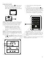
1. Remove battery access cover (A) on back of monitor
and install 2 AA batteries. (Observe correct battery
polarity which is embossed in the bottom of the
battery compartment). Replace battery access cover.
2. The wireless monitor does not have an on/off
switch. When batteries are installed correctly,
the GENERATOR READY green LED light will flash
once every 7 seconds indicating the status of the
generator.
NOTICE
If communication does not begin upon placing the
generator in AUTO, installing batteries, and pressing System
Update, the monitor may need to be re-linked. To link, follow
Steps 3 through 6.
3. Locate the MENU AND ESCAPE buttons on the control
panel (B) . Press and hold for 3 seconds to enter the
linking mode.
4. “LINKING MODE” will scroll across the generator
control panel.
5. Locate and hold the SYSTEM UPDATE button (C) on
the wireless monitor for 5 seconds. All 3 LEDs will flash
until the monitor links to the generator. Once it links,
the monitor will display the current state. The monitor
will try to link for 1 minute. (This step can only be
completed when the generator is in Linking Mode).
6. Once the link has been confirmed, press the OK
button on the generator control panel to exit or the
control board will turn off linking after 5 minutes. The
generator will now communicate with the wireless
monitor.
NOTICE
It may take up to 1 minute for the monitor to begin
displaying the generator status correctly.
DEALER
NAME
DEALER
PHONE
generator power
service needed
generator ready
system update
1 low battery voltage
2 low fluid level
3 under/over voltage
4 engine does not start
part #: 316196 fcc id: MCQ-XBS2C IC id: 1846A-XBS2C
5 low frequency
6 engine overspeed
7 high temperature
8 transfer switch
# of flashes service needed
a
ok
menu
esc
auto
off
manual
B
B
DEALER
NAME
DEALER
PHONE
generator power
service needed
generator ready
system update
1 low battery voltage
2 low fluid level
3 under/over voltage
4 engine does not start
part #: 316196 fcc id: MCQ-XBS2C IC id: 1846A-XBS2C
5 low frequency
6 engine overspeed
7 high temperature
8 transfer switch
# of flashes service needed
c
a
B
c
NOTICE
The wireless monitor was linked to the generator at
the factory. Communication will begin upon the installation
of the batteries and the generator being placed in AUTO
mode. You may need to press System Update one time.
NOT
for
REPRODUCTION
Summary of Contents for 20 kW Home
Page 10: ...10 Intentionally Left Blank N O T f o r R E P R O D U C T I O N ...
Page 41: ...41 NOTES N O T f o r R E P R O D U C T I O N ...
Page 42: ...42 NOTES N O T f o r R E P R O D U C T I O N ...
Page 43: ...43 Schematic Diagram Schematic Wiring Diagrams N O T f o r R E P R O D U C T I O N ...


