Masoneilan Model 4411 Electropneumatic Transducer Instruction Manual | 3
© 2015 General Electric Company. All rights reserved.
To meet the EMC specifications, screened cable should be used
for installation� The cable screen should be connected to the
internal earth bonding point of the I/P� An earth strap should
also be connected from the external earth bonding point of
the I/P to a common earth point� The cable screen should
not
be connected at the signal source when used in Intrinsically
Safe (IS) environments� The I/P has been thoroughly tested in
accordance with:
Electromagnetic compatibility (EMC)
Generic Standards – Immunity for industrial environments
Electromagnetic compatibility (EMC)
Generic Emissions Standard – Industrial environment
Please consult wiring diagram for further information� The
results obtained from these tests show that with the screen
arrangement shown in the installation diagram, the typical
sustained output pressure shift is <+/-5% full scale� Consult
supplier for further details�
Instrument Mounting
The converter can be mounted directly onto a valve, onto any
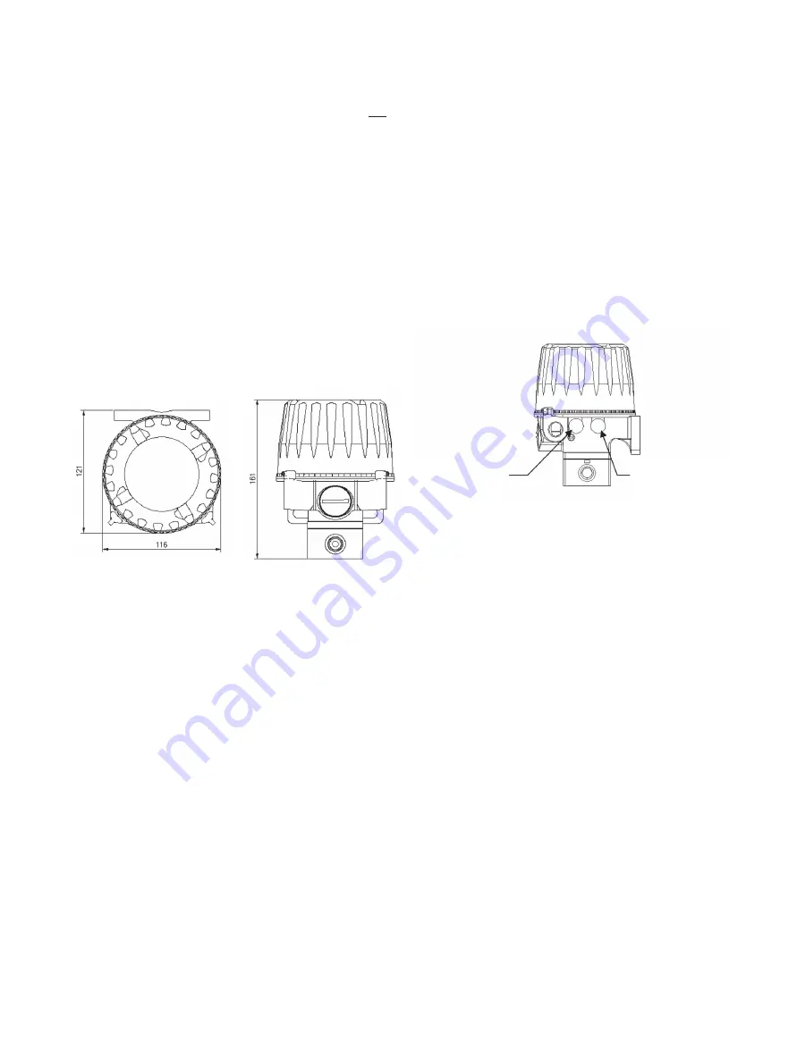
suitable flat surface, or onto 2” (50mm) pipe� Dimensional details:
Figure 2
These converters will operate in any position, with slight
re-calibration adjustments, normal operation is in the upright
position, i�e� with the screwed lid horizontal� The unit is weather
resistant when the lid is removed for connection or calibration,
but should not be left uncovered during operation or for
extended periods of time� They are unaffected by shock and
vibration, but severe vibration environments are best avoided�
The instruments are protected against environmental effects,
to a level of Type 4X (IP66)� Sensible positioning should be used
if the local environment is severe�
Temperature compensation is designed into these converters
which will operate over a range from –40° to +85°C (-40° to
+185°F)� Maximum life is obtained if extreme temperature cycling
is avoided� In extreme direct sunlight, sun-shading is advised�
The pneumatic exhaust and the bleed are routed through the
baffles� The baffles must not be blocked with paint and/or
plastic sheeting etc�
Captured Bleed Version
The baffles and the baffle cover are fitted to maintain the
adequate Ingress Protection (IP) rating of the instrument�
Removal of these protective parts will invalidate the IP and the
NEMA 4X rating of the instrument�
For captured bleed installation, remove the baffle cover and
unscrew both the baffles, fit 1/8" NPT fittings to two separate
lengths of pipes, to exhaust and bleed gas to a safe area
installation�
Vented gas from the enclosure through bleed port must not
be re-circulated and introduced back into the process stream�
Exhaust port installation must not have any restriction to
create backpressure to cause instrument to malfunction�
Instrument installation for captured bleed version must be
under the installer’s discretion�
Note: Exhaust Port is nearer the conduit entry (LH side)
Enclosure Bleed Port is on the RH side. (See Figure 3.)
Figure 3
Pneumatic Installation
These instruments are recommended for use with clean, dry,
oil free instrument grade air to BS�6739:1986 or ANSI/ASA-57�3
1975 (R1981)�
Dew Point:
At least 10°C (18°F) below (-40°C) minimum
anticipated ambient temperature�
Dust:
Filtered to below 50 microns�
Oil Content:
Not to exceed 1ppm mass�
The instrument is factory calibrated with a supply pressure of 30
psig (2 bar) ±10%� Operation is possible at any pressure between
18 and 150 psig (1�3 to 10 bar), though recalibration may be
necessary towards these limits to maintain specified accuracy�
The inlet and outlet ports are threaded 1/4" NPT female and
suitable fittings should be used� For most installations 1/4"
(6mm) pipe will be adequate� If a large actuator, high flow
rates or long pipework is necessary then a larger diameter
should be used�
Plastic tubing, e�g� Nylon is preferable where circumstances
permit, since it is normally very clean internally� In all cases,
purge the supply pipework before connection to the converter�
Two gauge ports are provided to facilitate direct mounting of
a pressure gauge� To use one of these ports remove the plug
(using a 1/4" or 3/16" Hexagon Key) in a de-pressurized state,
and connect the gauge� The ports are threaded 1/4" NPT at
the back of the unit and 1/8" NPT at the front�
Exhaust Port
Enclosure Bleed Port


