Star
t-Up Guide
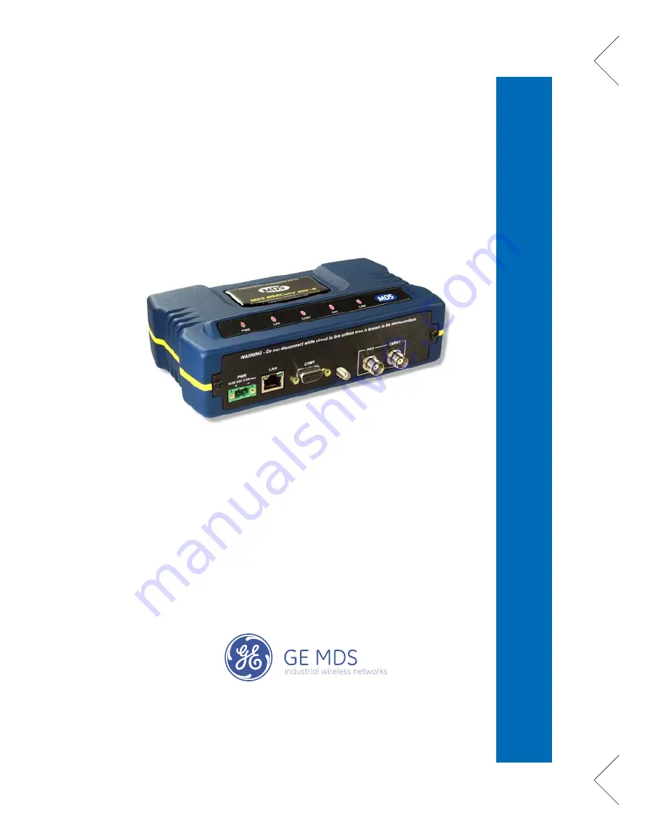
Wireless IP/Ethernet Transceiver
Covering all AP and Remote Units
including Mercury 900, 3650, and Option Set 1 Remotes
MDS 05-4558A01, Rev. C
December 2008
MDS Mercury
™
Series
Page 1: ...Start Up Guide Wireless IP Ethernet Transceiver Covering all AP and Remote Units including Mercury 900 3650 and Option Set 1 Remotes MDS 05 4558A01 Rev C December 2008 MDS Mercury Series ...
Page 2: ...r Normal Operation 7 Resetting to Factory Defaults Use with Care 8 AIMING DIRECTIONAL ANTENNAS 8 Procedure 9 TRANSMITTER POWER AND ANTENNA TEST 10 Procedure 10 TROUBLESHOOTING 11 SPECIFICATIONS 14 TECHNICAL ASSISTANCE 16 FACTORY SERVICE 16 Copyright Notice This publication is protected by U S A copyright law Copyright 2008 GE MDS All rights reserved The center of this guide contains a chart with a...
Page 3: ... INSTALLATION OVERVIEW There are three main requirements for installing the transceiver ade quate and stable primary power a good antenna system and the cor rect interface between the transceiver and the data device The Installation Setup Chart center of this guide shows a typical Remote installation Access Point and mobile Remote stations typically use omnidirectional antennas whereas fixed site ...
Page 4: ...cket screws Screws extending farther than 1 4 inch 6 mm into the case may cause internal PC board damage Step 2 Install the Antenna To minimize RF interference the antenna should be mounted at least nine inches 23 cm from the connected device s sensors and other external components of the system Additional information on antenna selection and installation is provided in the Mercury Reference Manua...
Page 5: ...protection NEC Class 2 rating to protect against a short circuit between its output terminals and the radio s power connector NOTE Typically it takes about 30 seconds for the transceiver to fully power up and may take several minutes to associate with another unit especially if GPS is required for time synchroni zation Step 4 Review the Transceiver s Configuration There are two key settings that m...
Page 6: ... on AP locations file which contains GPS coordinates to prede termine or preselect which AP to hop with Frequency 3650 model only Operating frequency in MHz TDD Sync Mode AP only Selections are Free Run Prefer GPS and GPS Required For single channel operation the TDD Sync Mode can be set to Free Run or GPS Required Using GPS Required synchronizes the AP s transmissions to the GPS timing When the f...
Page 7: ...m the default entry of MDS Mercury This can be changed under the Radio Configura tion Menu for both AP and Remote f Review other settings and make changes as necessary such as the unit password IP address and security g Under the Radio Configuration Menu at the Access Point set verify the following Transmit Power Settable from 30 dBm to 30 dBm AP 0 dBm to 30 dBm Remote 20 dBm for 3650 models Recei...
Page 8: ...ll Units Observe the transceiver s LED panel See Installation Setup Chart for the proper indications In a normally operating system the radio will typically become associated in about two minutes from start up At the Access Point a If the Access Point unit is the first unit you are installing send a PING command to it through the LAN port This verifies basic LAN connectivity b If you have already ...
Page 9: ...verify communications link integ rity with the Access Point d After the PING is successful connect the terminal equipment to the radio s data port and verify normal operation If all checks are OK you are finished with the installation at this site Resetting to Factory Defaults Use with Caution Selecting Maintenance Tools Reset to Factory Defaults sets all trans ceiver parameters back to their fact...
Page 10: ... Date Format Time Model Device Names Console Bd Rt UTC Time Offset Device Security Wireless Security Event Log Packet Statistics GPS Status Wireless Ntwk Stat Intl Radio Stat RM Performance Trend Manage Certif RADIUS Configuration Starting Information Screen Read Only Status Redundancy Configuration AP Redundancy Config Ntwk Event Triggers Radio Event Triggers Hdwr Event Triggers Red Config Option...
Page 11: ...s s hould be seen within 30 seconds of power up WR Lights continuouslyL AN On or blinks intermittently LINK On or blinks intermittently Remotes if associated U se PING command to test basic data link integrity between Access Point and Remotes I f the PING command is successful connect the RTU data equipment to the data port and verify normal operation I f the LINK LED on Remotes is not on after 2 ...
Page 12: ...3 Read the RSSI level at the Remote Main Menu Performance Information Internal Radio Status 4 Optimize RSSI by slowly adjusting the direction of the antenna Watch the RSSI indication for several seconds after making each adjustment so that the RSSI accurately reflects any change in the link signal strength The less negative the number the stronger the signal 5 View the Wireless Packets Dropped and...
Page 13: ...as a 10 minute timer after which it will return the transceiver to normal operation The Test Mode can also be terminated manually via the menu 3 Set the transmitter RF output power to 28 dBm Main Menu Radio Configuration Transmit Power NOTE The Test Mode RF power setting does not affect the output level during normal operation 4 Activate key the transmitter Main Menu Maintenance Tools Radio Test T...
Page 14: ...ving common system difficul ties using the radio s LEDs as a guide Table 2 on Page 13 provides guidance for using the Menu System as a tool If problems cannot be resolved using the guidance provided here review the GE MDS web site s technical support area for recent soft ware firmware updates general troubleshooting help and service information Additional help is available through our Technical Su...
Page 15: ...andwidth and pattern offset e Wrong encryption settings The Encryption Enable and Encryption Phrase must match on the AP and Remote f Wrong device authentication settings Verify settings match on AP and Remote LAN LED not lit a Verify the Ethernet cable is connected at both ends b Verify that the appropriate type of Ethernet cable is used straight through or crossover as required c Verify setting ...
Page 16: ...IP data to WAN a Verify your IP settings b Use the PING command to test communication with units in the local radio system c If successful with local PING attempt to PING an IP unit attached to another radio d If successful with the LAN PINGs try connecting to a known unit in the WAN ExcessiveWireless Retries Possible Radio Frequency Interference RFI a If omnidirectional antennas are used consider...
Page 17: ...kg 2 2 lb Case Die Cast Aluminum RADIO CHARACTERISTICS GENERAL Frequency Band Mercury 900 902 928 MHz Industrial Scientific Medical ISM Band Mercury 3650 3650 3700 MHz FCC Registered Band TRANSMITTER RF Output connector Mercury 900 30 to 30 dBm Mercury 3650 0 to 20 dBm Increments of 1 0 dB set by user Duty Cycle Continuous Output Impedance 50 Ohms RECEIVER Type Double conversion superheterodyne Se...
Page 18: ...1 Div 2 Industry Canada RS 210 PROTOCOLS Ethernet IEEE 802 3 Spanning Tree Bridging VLAN IGMP TCP IP DHCP ICMP UDP TCP ARP Multicast SNTP TFTP Serial Encapsulation over IP tunneling for serial async multidrop protocols includ ing Modbus DNP 3 DF1 BSAP MANAGEMENT HTTP HTTPS TELNET SSH local console SNMPv1 v2 v3 MIB II Enterprise MIB SYSLOG MDS NETview MSTM compati ble ...
Page 19: ...n the outside of the ship ping box and on any correspondence relating to the repair No equip ment will be accepted for repair without an SRO number A statement should accompany the radio describing in detail the trouble symptom s and a description of any associated equipment normally connected to the radio It is also important to include the name and telephone number of a person in your organizati...
Page 20: ...GE MDS LLC Rochester NY 14620 General Business 1 585 242 9600 FAX 1 585 242 9620 Web www GEmds com 175 Science Parkway ...