Rack Cards
Rack cards are designed to be installed in one of Fiber Options’
19-inch (483-mm) EIA standard card-cage racks, either the
515R1 or the 517R1. They may also be supplied in the 502R
standalone rack card enclosures. Follow these steps after per-
forming MODULE SETUP procedures.
515R1 and 517R1 Card Cage Racks
CAUTION:
Although rack cards are hot-swappable and may be
installed without turning off power to the rack, Fiber Options rec-
ommends that the power switch on the rack power supply be
turned OFF and that the rack power supply is disconnected from
any power source.
1. Make sure that the card is oriented right-side up, and slide it
into the card guides in the rack until the edge connector at the
back of the card seats in the corresponding slot in the rack’s con-
nector panel. Seating may require thumb pressure on the top and
bottom of the card’s front panel.
CAUTION:
Take care not to press on any of the LEDs.
2. Tighten the two thumb screws on the card until the front panel
of the card is seated against the front of the rack.
502R Standalone Enclosures
CAUTION:
Although rack cards are hot-swappable and may be
installed without turning off power to the rack, Fiber Options rec-
ommends that the power switch on the rack power supply be
turned OFF and that the rack power supply is disconnected from
any power source.
1. Look inside the enclosure to determine the location of the
socket for the edge connector. Orient the card so that it will seat
in the socket, and slide it into the enclosure until the edge con-
nector at the back of the card seats in the socket Seating may
require thumb pressure on the top and bottom of the card’s front
panel.
CAUTION:
Take care not to press on any of the LEDs.
2. Tighten the two thumb screws on the card until the front panel
of the card is seated against the front of the rack.
MODULE SETUP
General
Determine the data formats required for input and output. The
input and output formats may be the same or different, as
described in the next section.
Data Selection
NOTE:
The DATA SELECT switch on standalone units, or
SW1 on rack cards, is shipped in the Disabled setting.
Using the rotary DATA SELECT switch, select a valid data for-
mat according to the DATA SELECT settings shown in Figure 3.
See Figures 4 through 6 for the location of the DATA SELECT
switch.
NOTE:
If the link is going to support RS-485, refer to RS-485
APPLICATION NOTES on page 10.
www.fiberoptions.com
free phone: 800.342.3748
free fax: 877.342.3732
2
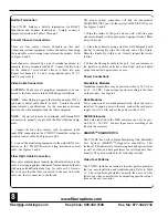
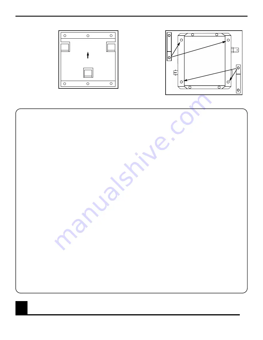
FIGURE 2: OPTIONAL SECURITY CLIP PLACEMENT
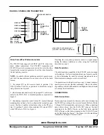
FIGURE 1: MOUNTING PLATE
Security clip
attaches to the
rear of the
module via
any of these
four screws.
DO NOT
mount the clip
to any other
screws on the
module.
Secure the
module in
place by then
screwing the security clip to the mounting surface, using a
screw suitable for the selected surface.
Mounting plate
attaches to selected
surface with six
suitable screws.
Standalone mod-
ules are mounted
by sliding it onto the
plate’s hooks until
firmly seated.
The module can be
easily removed and
remounted.


