Kalatel CBR-PB3-WD 13 0150-0261A
5 Detailed Installation
Steps
5.1 PB3 Physical Installation
1. Disconnect the existing Receipt Printer cable from the back of the POS
system and install the ECR Interconnect Cable (4310-0078A) to the
Receipt Printer as shown on page 11.
2. Reconnect the Receipt Printer Cable to one of the D9F connectors on
the ECR Interconnect Cable as shown
on page 11.
3. Connect the other end (DB9F) to the DB9M connector on the PB3 unit.
4. Connect the PB3 Power Supply to the unit.
If only one (1) PB3 unit (one cash register) is to be connected, skip to
Step 8
below.
5. If more than one cash register interface is to be installed repeat steps 1-
4 above for each additional cash register.
6. Connect each PB3 unit together by using an RS-485 cable with RJ-45
connectors on each end. Connect to either receptacle on Port 0 to
interconnect the PB3 units using an “in” and “out” method. (For details
on the RS-485 cable, review the cable specifications in Section 13).
Note: This cable shall be provided by the installer.
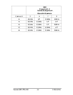
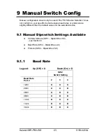
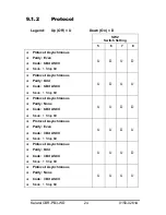
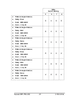
7. Confirm that each PB3 has the proper termination setting per the
instructions on page 12.
8. Connect all ECR cameras to their associated inputs on the DVMRe unit
(ECR#1 = Camera 1 Input, ECR#2 = Camera 2 Input….)
9.
Connect the PB3 closest to the DVMRe using the supplied cable (4310-
0043B) from Port 1 (RJ45 outer receptacle) of the PB3 to the RS232/2
port on the DVMRe unit.


