background image

User Manual            


                                                                                Family                 

MAN10239-02 30 


Printer Setup (with configuration pages)  


The Printer Setup is used to configure the printer parameters and to print a Self Test page, to check the 
settings and the printer installation, and to perform the Print Offset Tuning. 
The default configuration of this printer matches most of the commonly used environments, but it may be 
necessary to change some printer parameters.  
With this printer you print the forms for the setup, you fill them in, and then you insert them back into the 
printer for reading. 
Once the printer reads the form, the new values are set. 
The following is the complete description of the Setup Procedure with configuration pages. 
 

Entering the Printer Setup Mode 


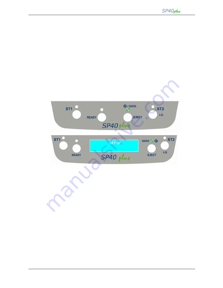
To enter the Printer Setup Mode press and hold the READY key pressed for at least 1 second while 
powering the printer on. The printer enters the Setup Mode. 
The leds ST1, ST2 and READY are unlit, the DATA led is flashing.  
SETUP is displayed in the models with LCD. 


You can now: 
 

  Print the Self Test. 

  Print one of the #6 Printer Setup Forms (Configuration, Program1, Program2, Program 3, Program4 

and the Offset Tuning). 

  Load a filled Setup Form to store the Setup parameters. 

  Insert a prefilled Printer Setup Form to set the corresponding Setup values. 


Printing the Test Page 

 
The Self Test page is useful to test, if the printer has been correctly installed, and allows to see the current 
parameter settings.  
 

1.  With the printer in the Setup Mode, insert a blank 80gr/m2 single sheet in A4 or Letter format. 
2.  The printer loads the sheet and stops. 
3.  Press the READY key again. 

 
The printer prints the Self-Test page. Check that the printout is correct and the Setup parameters are correct. 
The following printout examples show the Printer SELF TEST default values. 
Once the self-test is finished, the printer remains in Setup Mode. 

Summary of Contents for SP40 PLUS series

Page 1: ...User Manual for family MAN10239 02 ...

Page 2: ......

Page 3: ...rcial environment This equipment generates uses and can radiate radio frequency energy and if not installed and used in accordance with the instruction manual may cause harmful interference to radio communications However there is no guarantee that interference will not occur in a particular installation If this equipment does cause harmful interference to radio or television reception which can b...

Page 4: ...Installation 9 Compuprint CDC RS 232 emulation driver Installing the Ribbon Cartridge 10 installation 55 Installing the Tractor Unit 14 SP40Plus Remote Setup Installation 56 Connection to the Host 16 LAN Setup 61 Installing the power cable 17 Using the SP40Plus Remote Setup Tool 61 Paper Handling 18 Using the LANPAR parameters only Loading Paper 18 through parallel interface 62 The Operator Panel ...

Page 5: ...82 Paper specifications for Fanfold 87 Hexadecimal Dump 82 Serial Interface 89 Paper Specification 83 Magnetic Media 90 Cut Sheets 83 Magnetic Ink Character Recognition 90 Passbooks 84 Magnetic Strip Read Writer 90 Passbooks with Horizontal Fold 85 User Information according the European Directive 2002 95 EC and 20003 108 EC 93 ...

Page 6: ...SP40Plus basic dual USB I F PRT0627 With LCD and Dual USB 2 0 I F SP40Plus basic special PH PRT0620 THN No LCD and thin wheel PH SP40Plus LAN PRT0626 LAN With LCD LAN interface SP40Plus MSRW MICR PRT0630 With LCD and MSRW MICR function SP40Plus SCANNER PRT0631 With LCD and SCANNER function SP40Plus MULTIFUNCTION PRT0632 With LCD and MSRW SCANNER function SP40Plus TRACTOR PRT0626 TT With LCD LAN in...

Page 7: ...66 Cyrillic CP867 Turkish CP876 OCRA CP877 OCRB CP1098 Farsi Arabic CP1250 Central Europe CP1251 Cyrillic CP1252 Windows Latin1 Ansi Gost Tass Mazowia ISO 8859 1 2 3 4 5 6 7 8 9 15 96GREEK Ukrainian ID 12 ID 14 ID 17 Roman 8 Sanyo Ku Philip Character set Olivetti CS000 CS010 International CS020 Germany CS030 Portugal CS040 Spain1 CS050 Denmark Norway CS060 France CS070 Italy CS080 Sweden Finland C...

Page 8: ... RGB 256 grey scale levels up to 600 DPI Twain compatible MSRW Magnetic Strip Read Write 4bit code reading speed up to 13 inch sec decoded Characters ASCII 30 3F Field duplication Supported emulations DIN32774 ANSI IBM 3604 and Borroughs MICR Micr reading up to 27 inch sec E13B and CMC7 alphanumeric and numeric modes supported Optional Interfaces Ethernet 10 100 LAN 2nd RS232 2nd USB 2 0 up to 3 U...

Page 9: ...lier o Ribbon Cartridge o Power Cable o CD ROM with printer documentation and drivers o Quick Reference Guide Only for tractor model o Ribbon Cartridge o Power Cable o Tractor Unit o CD ROM with printer documentation and drivers o Quick Reference Guide Always keep the packing material in a safe place as you must repack the printer into it when you need to move it ...

Page 10: ...unless it is expressly indicated in this manual Front Views M Mo od de el l w wi it th h o op pe er ra at to or r p pa an ne el l w wi it th ho ou ut t d di is sp pl la ay y M Mo od de el l w wi it th h o op pe er ra at to or r p pa an ne el l w wi it th h d di is sp pl la ay y ...

Page 11: ...User Manual Family MAN10239 02 6 Front Views for tractor unit ...

Page 12: ... by the models the available interfaces can be different Optional interfaces available parallel 2x Serial USB 2x USB Hub LAN Rear view for tractor unit For the tractor model only in the rear part of the printer together with the AC power connector and all the interface connectors there is tractor unit connector and gear visible on the left side ...

Page 13: ...User Manual Family MAN10239 02 8 Inside view Inside Views ...

Page 14: ...le The location must be sturdy horizontal and stable Your printer must not be exposed to direct sunlight extreme heat cold dust or humidity When printing on standard paper formats the paper comes out partially on the rear side of the printer Make sure that behind the printer there is sufficient clearance to correctly move the paper On the left are showed the minimum spaces for basic models while o...

Page 15: ...ings this printer accepts only original Compuprint ribbon cartridges Therefore if you install a not original cartridge the printer may not work 1 Remove the cartridge from its bag 2 Unhook the green ribbon mask from the cartridge pins 3 Open the printer cover The print head will automatically move in the middle of the printer ...

Page 16: ...t side of the printer 5 Unhook the green lever with the left hand towards the rear of the printer in the open position 6 Then rise up the lever to its maximum position in order to completely open the head assembly 7 Check for the click which means the correct open lever position showed in the inset picture ...

Page 17: ... knob in the direction of the arrow to tighten the ribbon 10 Insert the upper cartridge pins onto the corresponding grooves on both sides of the upper mechanical frame 11 Then push the lower cartridge pins into the corresponding lower grooves on both sides of the upper mechanical frame until it clicks into place ...

Page 18: ...14 Turn the tension knob in the direction of the arrow to tighten the ribbon 15 Carefully pull down the green lever following the step 3 4 and 5 in reverse order in order to securely close the Upper Mechanical Frame If you do not LOCK the Upper Mechanical Frame the printer does not print correctly 16 Close the printer cover Remark The printer detects the Ribbon Genuine type and the amount of print...

Page 19: ...in other printer unit because it requires a paper sensor calibration procedure through technical diagnostic 1 Align the tractor unit in the rear side of the printer 2 Locate the RJ plug in the left side of the tractor unit and gently insert it in the proper connector of the printer until it clicks 3 Then align the tractor unit metal pins over the respective slots of the printer ...

Page 20: ... lock lever while put the tractor unit in position until they sound a click 5 Open the right tractor lever and move the right tractor as the paper width Open the tractors cover and install the paper on it 6 The printer is now ready to print on the continuous module ...

Page 21: ...0 full speed interface 4 Other optionally available ports 10 100T Wired LAN USB 2 0 high speed dual serial RS232 C Proceed as follows Make sure that both the host and the printer are turned off Identify the connector for the interface you want to plug and firmly insert the cable into it Fix the cable by means of the corresponding hooks or screws on either side of the connector Parallel Interface C...

Page 22: ...ble connector and the rating plate on the rear side of the printer Always use a grounded outlet 2 Insert the power cable into the connector on the printer and the other end into a convenient mains outlet 3 Press the key on the right side of the printer front to power the printer on ...

Page 23: ... rules described in the following paragraph The paper alignment sensors determine the alignment of the upper paper margin adjusting it if necessary Loading Paper The inserted documents must not have folds tears pins clips staples or any foreign material If you insert damaged documents or paper with foreign material you can seriously damage the printer Before inserting a passbook into the printer o...

Page 24: ...MAN10239 02 19 The different type of loaded media must be loaded with respect the area merkers highlighted on the front cover flap The document may not exceed the limits of the paper stand Correct fanfold loading position ...

Page 25: ...User Manual Family MAN10239 02 20 Correct cheque loading position CMC7 codeline side on the bottom Correct passbook loading position magnetic codeline side on the bottom ...

Page 26: ...u can easily check the printer status and select the functions Some models are equipped with a wide LCD 2x16 characters display for an easiest and visible status and or error condition There are four types of operator panels showing in the figures below Meaning of the leds are the same for all models Meaning of the functions keys are the same for all models except the tractor model ...

Page 27: ... in formware upgrading procedure Toggles the printer between Ready on line and Local off line status If pressed in the Printer Setup mode the printer prints the Self Test Page See printer Setup later in this manual When pressed while powering the printer on selects the Printer Setup Mode When pressed while powering the printer on with READY key select the T D mode diagnostic Pressing this key when...

Page 28: ...r is in Setup Mode this led indicates which setup page is selected for printing See Printer Setup later in this manual On if the printer is powered on without data Off if the printer is powered off Blinks if the printer has data traffic or data in the buffer Blinks if the printer is in Setup Mode See Printer Setup later in this manual Lit when the Letter Quality print mode is selected Unlit when t...

Page 29: ... a Set Up operation selection See Printer Setup later in this manual REMOTE SETUP FROM USB The printer is Setup via Remote tool connection NVM CHANGED The firmware of the printer has been updated and the NVM values have been resored to the default parameters Specific messages for LAN and tractor models INIT LAN The LAN initialization phase is ended PRINTER READY LOADING MEDIA The printer is in nor...

Page 30: ...2000 Windows 2003 32 and 64 bit WindowsServer 2008 32 and 64 bit Windows Vista 32 and 64 bit Scanner Driver 32 and 64 bit TWAIN CDC Driver for Windows 98SE XP CDC Driver for Windows 2000 Vista Windows 7 Virtual COM on USB 32 and 64 bit PrintPort for TCP IP for W98SE Unix Linux Windows Drivers printer scanner and CDC For Windows O S from XP and later a specific installation Setup has been issue Com...

Page 31: ...r supporting Plug Play utility and the Driver will be automatically installed For O S Windows XP and before it is necessary anyway to install the printer by open Control Panel Printer and Devices add printer And follow the masks to choose printer model port and the folder where the driver is located For the SP40plus family all the drivers are in the folder source Drivers Compuprint SP40_SP40Plus_S...

Page 32: ...test one Twain Driver To be used in application requiring twain driver a specific installation Setup has been issue It is called Twain Install exe It is located in the folder source Drivers Compuprint SP40_SP40Plus_SP40PlusT TWAIN DRIVER Double click on it Initial mask of TWAIN driver installation Setup ...

Page 33: ...ucupsdrv_linux_v1 0 tar installation file A specific Debian GNU Linux ubuntu installation procedures is present in the same folder CDC Driver To be used in SP40Plus Setup application requiring a driver converting the serial port in a USB port Virtual COM on USB Driver To be used in 4722 financial protocol in USB high speed port The latest printer drivers of all Compuprint printers can be found on ...

Page 34: ...f the printer connected through the serial interface the transmission parameters set for the printer must match the values set for the host In case you need to modify the standard parameters see Printer Setup or Remote Printer Setup later in this section USB Interface Once the Compuprint SP40Plus driver has been correctly installed on the host printer can be immediately used with USB port In case ...

Page 35: ...e powering the printer on The printer enters the Setup Mode The leds ST1 ST2 and READY are unlit the DATA led is flashing SETUP is displayed in the models with LCD You can now Print the Self Test Print one of the 6 Printer Setup Forms Configuration Program1 Program2 Program 3 Program4 and the Offset Tuning Load a filled Setup Form to store the Setup parameters Insert a prefilled Printer Setup Form...

Page 36: ...User Manual Family MAN10239 02 31 Self Test SP40Plus basic model ...

Page 37: ...User Manual Family MAN10239 02 32 Self Test SP40Plus LAN model ...

Page 38: ...User Manual Family MAN10239 02 33 Self Test SP40Plus MULTIFUNCTION model ...

Page 39: ...User Manual Family MAN10239 02 34 Self Test SP40Plus TRACTOR model ...

Page 40: ...ause the other are exactly the same except for the marker The printer Setup forms contain all printer parameters and the values that can be set Onl one selection can be done for each line The current value is indicated by an asterisk For a detailed description of the parameters and the settings see Setup Parameters later in this manual Each Setup form is identified by a marker in the upper left co...

Page 41: ...User Manual Family MAN10239 02 36 Configuration Setup SP40Plus basic model ...

Page 42: ...User Manual Family MAN10239 02 37 Configuration Setup SP40Plus LAN model ...

Page 43: ...User Manual Family MAN10239 02 38 Configuration Setup SP40Plus MULTIFUNCTION model ...

Page 44: ...User Manual Family MAN10239 02 39 Configuration Setup SP40Plus TRACTOR model ...

Page 45: ...User Manual Family MAN10239 02 40 Program Setup SP40Plus basic model ...

Page 46: ...User Manual Family MAN10239 02 41 Program Setup SP40Plus LAN model ...

Page 47: ...User Manual Family MAN10239 02 42 Program Setup SP40Plus MULTIFUNCTION model ...

Page 48: ...User Manual Family MAN10239 02 43 Program Setup SP40Plus TRACTOR model ...

Page 49: ...ferent printer models Please refer to the proper Setup Configuration and Program sheet to identify the correct one for each printer model Configuration Setup SP40 PLUS Code Version xxxx Setup Parameter Values Description RESTORE TO MFG No all config prog 1 prog 2 prog 3 prog 4 The selected values are not set to factory defaults The values set in all printer setups are reset to factory defaults The...

Page 50: ...this setting is ignored IGNORE PE Enabled disable Selects whether the printer signals the paper empty condition disabled or not enabled on the busy line AUTOFEED SIGNAL Disable enabled The parallel interface uses enabled or does not use disabled the AUTOFEED signal SLCT IN SIGNAL Disable enabled The parallel interface uses enabled or does not use disabled the SELECT IN signal BUFFER CONTROL DTR SR...

Page 51: ...y Setup Parameter Values Description MSRW STANDARD Ibm6304 Din 32744 ANSI Burr 1 Burr 2 Selects the type of standard of magnetic data MSRW in use END SENTINEL F C Select the type of end sentinel for magnetic data DISPLACEMENT 1 180 Select the range minus or plus and the value n 180 of MSRW magnetic band displacement Example How to set the Displacement to 82 10x 0 1 2 3 4 5 6 7 8 9 1x 0 1 2 3 4 5 6...

Page 52: ...Values Description SPACE DETECT Disabled enabled Selects space detection of MICR EJECT Command Auto Select the mode of eject magnetic media RETRY Select the number of retry of the MICR band read Example How to set the Retry to 2 1x 0 1 2 3 4 5 6 7 8 9 ...

Page 53: ...cked font horizontal pitch hor pitch or both the font and horizontal pitch font hor pitch The locked settings cannot be changed via software commands FORM LENGTH Minimum 1 Maximum 255 Current 70 lines A4 letter A5 legal Sets the page length in number of lines or standard formats A4 Letter A5 or Legal If you select lines you must indicate the number of lines you want to set in the scheme below this...

Page 54: ...line to the tens and the third line to the units See the example below Example How to set the Right Margin to 121 RIGHT MARGIN 100x 0 1 10x 0 1 2 3 4 5 6 7 8 9 1x 0 1 3 4 5 6 7 8 9 Setup Parameter Values Description TOP MARGIN Minimum 0 Maximum 90 Current 0 10 x 1 x Sets the top margin in number of lines The values range between 0 and 90 To set the values combine the numbers considering that the f...

Page 55: ...UNIX Selects the character sets for the OLIVETTI protocol Selecting CODE PAGE it is possible to select one of the above Code Pages to be used with the OLIVETTI protocol OLIVETTI COMPRES 17 1 cpi 16 4 cpi 16 5 cpi 16 6 cpi Selects the compressed pitch in OLIVETTI protocol VERT RESOLUTION 1 216 inch 1 240 inch Sets the vertical character resolution used for the OLIVETTI protocols REFERENCE EDGE Left...

Page 56: ... yes When the printer receives a reset command if this item is set to yes the paper inserted in the printer is ejected If the item is set to no the printer performs only the reset command CUT SHEET EJECT On front on rear Selects wheter the cut sheet loaded into the printer is ejected toward the front or the rear of the printer FEED SPEED fast slow Selects the speed of the paper feed PARK MODE for ...

Page 57: ...ws to easily adjust the first line and the first printing column as follows 1 When the printer is in Setup Mode load a blank sheet into the printer press the ST1 key until the leds are in the configuration showed in previous SETUP STATUS table 2 Press ST2 key the following sheet will be printed 3 Fill in the marker corresponding to the value you want to set ...

Page 58: ...X X X X X X X X X Vertical Offset Tuning Vertical Offset Tuning VERT DEF POS HORIZ DEF POS Horizontal Offset Tuning FIRST PRINT POSITION Reading the Pre printed Setup Forms When the Printer Setup Forms have been filled in insert them back into the printer when the printer is in Setup Mode The printer is able to recognize the Setup Forms by means of the markers on these pages The printer reads the ...

Page 59: ...User Manual Family MAN10239 02 54 Printer Setup Flow Chart Printer OFF Printer Ready Setup Mode Parameters are set Self Test ...

Page 60: ...er through USB directly or RS232 C Serial connection directly or via a serial USB adapter This chapter described how to install the driver and the utility This utility can be used also for the Firmware downloading but this features is not covered with this manual Compuprint CDC RS 232 Emulation Driver installation If the printer is connected through the USB interface and the Setup mode is running ...

Page 61: ...l be found SP40Plus Remote Setup Tool installation Once the Compuprint CDC RS 232 Emulation driver has been installed found the Setup exe file and double click on it Follow the steps displayed in the below masks in order to correctly install the utility The utility will ask where install the program and choose the program group ...

Page 62: ... will be run The SP40Plus Remote Setup Tool is now at 2 0 25 release When this utility is running the following home mask will be displayed In the left top side under Selection Printer Type there is the selection of 1 Set Program for SP40 family 2 Set Program for Sp40Plus family default 3 Download FW In the right top side there is the physical serial interface setting parameters selection ...

Page 63: ...le below a Serial USB adapter is connected to the serial line of the printer it has been seen by the host as COM6 port and this port will be displayed and selected in the Setup port selection When select the available port the right side function keys available will be highlighted In the figure on the left the functions available are 1 Read NVM 2 Restore MFG 3 Refresh List of Interfaces When the R...

Page 64: ...fter a short time time to recover data from NVM the tool will show 1 The printer FW details ID Model Release 2 All the parameters of the printer as printed in the Self Test At this point also the Write NVM key will be activated The following masks will show the complete list of Setup CONFIGURATION SETUP LAN INTERFACE SETUP ...

Page 65: ...e the default configuration name as wnvm dmp The folder and the name will be changed This file will be send to the printer The configuration file dmp can be simply used to duplicate the same configuration on more printers SP40plus unit has to be powered on in normal mode connected to the PC through any active interface Centronics or Serial port and prompt copy file dmp lpt1 b command from a DOS sh...

Page 66: ...lel interface 3 Using the NetViewMaster Tool this tool can be used starting from the printer FW release 1 87 and require the lan parameters to be already set 4 Using any browser by access to built in webpages of the printer require the lan parameters to be already set Using the SP40Plus Remote Setup Tool This is how appear the LAN INTEFACE SETUP in a SP40Plus LAN printer with FW 1 87 installed Pag...

Page 67: ...OCATION string max 30 crt CONTACT string max 30 crt IP ASSIGN ARP fixed DHCP IP ADDRESS ip address NET MASK ip address DEF GATEWAY ip address WORKGROUP string max 15 crt SMTP disabled enabled MAIL SERV ADD ip address SENDER ADDRESS string max 48 crt DESTIN ADDRESS string max 48 crt HTTPD disabled enabled SMBD disabled enabled TELNET disabled enabled FTP disabled enabled LPR disabled enabled DIRECT...

Page 68: ...T LOCATION No location CONTACT No contact IP ASSIGN fixed IP ADDRESS 127 000 000 000 NET MASK 255 255 255 000 DEF GATEWAY 000 000 000 000 WORKGROUP P_NFFPS_TO SMTP disabled MAIL SERV ADD 000 000 000 000 SENDER ADDRESS No address DESTIN ADDRESS No address Command example ...

Page 69: ...ters may be configured as needed from the administrator s workstation 5 Firmware Updating provides a firmware downloading function to upgrade both the base and the LAN card firmware 6 Remote Operator Panel Management provides a virtual operator panel for the remotely connected printer at the administrator s workstation that allows to perform all functions normally achieved pressing the operator pa...

Page 70: ...s for the printer databases New Database To create a new database file Open Database To open an existing database Save To File To save the current database file The program prompts the user to enter a name for the file Exit To end the NetViewMaster Utility program 2 Edit Menu This menu allows you to manage the printer database contents folders printer devices configuration files or firmware downlo...

Page 71: ... range The printer find in the range are inserted into the existing Database Printers Net Scan new The NetViewMaster Utility searches for the connected printers within a specified IP address range by sending a burst of directed SNMP requests to each IP address within the range The current database is closed and a new database is created 5 Printer Operation Menu This menu allows Printer Configurati...

Page 72: ...mbols When clicking on it the object view toggles between the expanded and the collapsed view that is the details for the object are shown or hidden The printer in the database is ready and working normally The printer in the database is ready and working but a consumable is running out The printer will probably need an operator s intervention soon The printer in the database is in alarm or standb...

Page 73: ...the device discovery procedure the NetViewMaster Utility maps Compuprint Serial Matrix Printers for complete management getting the proprietary MIB objects supported Third parties vendors devices are mapped for basic status reporting only How to start Automatic Device discovery The first time automatic device discovery is started pressing the rightmost button Printer net scan new on the NetViewmas...

Page 74: ...te Panel Management icon 1 Selecting the Printer Configuration icon and the printer configuration is loading 2 Select the value of item In the Configuration menu is possible to Send Modified Value Send All Values Restore Default Config In the file menu is possible to Open an existing condiguration file Save the Configuration Exit ...

Page 75: ...e to see its built in web pages simply by digit the IP address on the browser This is the Home page The following Menu are available 1 Printer Configuration 2 Printer Status 3 Printer Reset 4 Product Support Printer Configuration page The following Menu are available 1 Configuration showed 2 Program 1 3 Program 2 4 Program 3 5 Program 4 6 LAN Setup 7 System ...

Page 76: ...gram 4 13 LAN Setup 14 System Printer Configuration page The following Menu are available 15 Configuration 16 Program 1 17 Program 2 18 Program 3 19 Program 4 20 LAN Setup showed 21 System When the change is submit to the printer the authotitazion with login and password is requested Login root Password root A warning message is displayed to advise next action ...

Page 77: ...10239 02 72 Reboot Page Message to advise the printer reset Printer Status Page System Menu Page It is possible to restore to default MFG values all the parameters Set the Serial Number for USB Set a new password in security ...

Page 78: ...llation Setup exe file is stored in the folder source SP40_SP40Plus_MFP_DOC_and_Example Demo SP40wrap Demo Installation Double click on it After the installation look at the Programs and run the SP40_mlt_if SP40 Mlt If Setup home page Home page of the Demo Tool SETUP MENU Setup Printer parameters Printer mode MSRW types and other selections MICR types and other selections ...

Page 79: ...or normal eject Set image crop windowing Set Front and rear image parameters Set data for MSRW Message when Write Passbook is run Mask for Read Passbook data Done Mask for Read Serial Done a serial interface must be physically connected The USB ID stored in NVM value is written on the left ...

Page 80: ...mily MAN10239 02 75 TESTS INDEX Print Document mask prompt to folder to select a printable file Mask for Read Cheque The CMC7 codeline read is written on the left This is the result after the Scan Document selection ...

Page 81: ...ser Manual Family MAN10239 02 76 This is the result after the Multi Scan Document selection After the scan action the Save with name for the multipage file in PDF format is done in the folder you select ...

Page 82: ...ters to be printed Prepare a new Compuprint genuine ribbon cartridge See Installing the Ribbon Cartridge RIBBON EXHAUST REPLACE RIBBON The ribbon cartridge installed has reached the 105 of the its nominal life Install a new Compuprint genuine ribbon cartridge See Installing the Ribbon Cartridge CARRIAGE ERROR The carriage movement has been stopped during printing causing print integrity Check for ...

Page 83: ...ects an error on one of the carriage movement during the initialization phase The problem may depends by the home carriage sensor initialization errors Check for the carriage free movement SOFTWARE FAULT SUPERVISOR The software of the printer detects a failure during the displayed phase The problem may depends by an internal software routine error SOFTWARE FAULT PARSER The software of the printer ...

Page 84: ... before in this manual Single Sheet Paper Jam In case a paper jam condition occurs proceed as follows 1 Open the printer cover And rise the upper mechanical frame as explained in the chapter Installing the Ribbon Cartridge page 5 2 Remove the jammed paper pulling it towards the front of the printer 3 In case it is not possible to remove the jammed paper because you cannot reach it with your hand o...

Page 85: ...orrect rotation of the ribbon as indicated by the arrow Replace the ribbon cartridge with a brand new one If the printout is light the problem could depend by the not correct installation of the ribbon cartridge Check for the correct insertion of the idle pivot in the ribbon rear hole and the correct ribbon fixation on the mechanical side If the printer stops to print without reason the problem co...

Page 86: ... a ribbon error the error could depend by the incorrect installation of the ribbon toward the rear contact located in the rear side of the ribbon If the printout is smudged check if the ribbon green support is correctly installed See the figure on the right ...

Page 87: ...pper mechanical assembly and clean the scan plastic surfaces with a soft damp cloth Do not use alchool Hexadecimal Dump The hexadecimal dump function is activated when the ST2 key is press at power on The printer enters in this functions and remains until it is powered off The hexadecimal dump shows all the characters sent by the host to the printer even the not printable ones as well as escape co...

Page 88: ...paper o It is preferable to use single and multiple documents with the fibre running in the insertion direction of the printing unit o Recycled paper is permitted on principle o It is preferable to print on multiple forms with a narrow glue strip or top gluing The gluing must not cause waving in the set of forms Cuts Sheets Insertion direction Print Area A B C C D E Dimensions Maximum Minimum A Fo...

Page 89: ...m 0 0071 in 0 28 mm 0 011 in Covers 0 18 mm 0 0071 in 0 46 mm 0 018 in o Passbooks with torn folded creased incomplete or warped pages or covers should not be used o Printing on or across holes edges cut outs or folds is not permitted o Passbook covers must be of uniform thickness under the printing area o The fold of all pages and the stitching must coincide with the cover fold The stitches shoul...

Page 90: ...ween print character position and left or right edge 3 0 mm 0 118 in D Distance between top edge of the document and top edge of first printed line 1 mm 0 0394 in E Distance between bottom of last printed line and bottom edge of the document 6 6 mm 0 26 in F Outer corner radius 9 35 mm 0 368 in G Distance from fold to bottom of the first printed line above the fold 3 5 mm 0 138 in H Distance from ...

Page 91: ...t to the left or right edge 3 0 mm 0 118 in D Distance from the top edge of the document to the top edge of the first printed line 1 mm 0 0394 in E Distance from the bottom of the last printed line to the bottom edge of the document 6 6 mm 0 26 in F Outer corner radius 9 35 mm 0 3681 in G Distance from the fold to the first character position beside the fold 3 5 mm 0 138 in H Distance from the fol...

Page 92: ...les 0 15 mm 0 06 inch tol M Deviation of horizontal holes on a distance of 254 mm 10 inch 0 125 mm 0 05 inch N Crimplock scratches type for multicopy 76 2 3 inch O Crimplock band type for multicopy 101 6 mm 4 0 inch Thickness single page 0 090 0 010 mm 0 004 inch Weight single page 60 gr m2 min Weight Multicopy 3 parts 50 gr m2 min Carbon paper 15 30 gr m2 Weight Multicopy 5 parts 50 gr m2 max fir...

Page 93: ...User Manual Family MAN10239 02 88 ...

Page 94: ...89 Serial Interface Connection RTS DCD Female connector 5 9 4 8 3 7 2 6 1 Solder side view GND To printer CTS To PC IBM compatible CTS DSR DSR DTR RX DTR Solder side view DCD TX RTS GND RI Female connector 5 9 4 8 3 7 2 6 1 RI RX TX ...

Page 95: ...he booklets according to the print line direction to be properly managed by the magnetic option Here below are reported the device technical specifications Recording Code BCD binary coded decimal 4 data bits 1 VRC parity control bits Recordable characters ASCII table 30 3F code Recordable formats DIN 32774 ANSI IBM 3604 Recordable track width 7 mm Read track width 2 mm Speed of media 340 mm sec Di...

Page 96: ...tamble 20 zero bits Start sentinel SOM B End sentinel EOM F or C Recordable characters 0 9 and E Recording direction Left to Right Center of vertical position 10 4 mm Horizontal start position 10 4 mm From the left edge Recordable characters number 36 max with field duplication Recording capacity 104 char Max control codes and separator included Bourroughs standard Bit density 161 210 Bit Per Inch...

Page 97: ...User Manual Family MAN10239 02 92 DIN ISO ANSI Standard Lay out IBM 6304 Standard Lay out BORROUGHS Standard Lay out ...

Page 98: ...chnology IT equipment to responsibly recycle their equipment when it is no longer needed Customer that needs to dispose this equipment must contact the produce and follow the collection framework available locally for the return recycling and recovery of WEEE Customer participation to the separate collection is important to minimize any potential effects on the environment and human health due to ...

Page 99: ......

Page 100: ...E SUBJECT TO CHANGE WITHOUT NOTICE This manual refers to various company and products by their trade names In most of the cases these designations are claimed as trademarks or registered tramarkers by their respective companies Copyright 2016 COMPUPRINT s r l Printed in Italy ...

Reviews: