background image

11

Guangcheng Technology

GCAN-PLC user manual

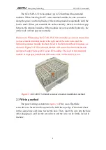
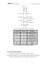
Figure 2.8

GCAN-PLC-510, Power terminal block

Terminal

Number

Definition

24V

1

Input 24V power

0V

2

GND power

+

3

IO positive power

+

4

IO positive power

-

5

IO negative power

-

6

IO negative power

PE

7

shield

PE

8

shield

Table 2.3

GCAN-PLC-510, terminal definition

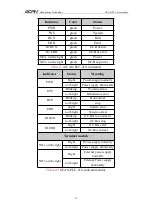
2.5 System status indicator

GCAN-PLC-510 has two sets of status indicators, contains 6

circular status indicators in the left area and 2 power indicators in the right area.

The specific indicating function of the indicator is shown in

table 2.4.

Summary of Contents for GCAN-PLC-510

Page 1: ...GCAN PLC 510 Programmable Logic Controller User manual Document version V4 02 2021 03 24...

Page 2: ...V1 00 2016 12 20 Create V2 01 2017 11 22 Add parameters V3 01 2018 01 22 Add protocol part V3 20 2018 07 18 Adjust structure V3 25 2019 3 21 Selection table update V4 00 2020 02 21 Update product para...

Page 3: ...status indicator 11 3 Communication connection 13 3 1 Serial connection 13 3 2 CAN connection 13 3 3 CAN Bus terminal resistance 14 3 4 PLC program running switch and reset button 15 4 Program operati...

Page 4: ...he inserted terminal module The GCAN PLC 510 is programmed according to the IEC 61131 3 standard using the OpenPCS programming system OpenPCS programming system provides a variety of debugging feature...

Page 5: ...er supply plus expansion power modules the number of expandable IO modules is up to 32 up to 32x8 DI DO points Transmit 4 PDOs CANopen and receive 4 PDOs CANopen Configuration mode is automaticconfigu...

Page 6: ...10 includes three communication interfaces a controller programming interface a set of controller power interface twosetsof I O power interfaces two sets of Shielding line interfaces Among them the co...

Page 7: ...on the left end of the controller counterclockwise to fix the left end of the controller on the guide rail The GCAN PLC 510 has a self locking mechanism that can effectively prevent equipment from fal...

Page 8: ...minal modul at the right end of the entire node and the terminal resistance module has been fixed to the bottom without looseness as shown in Figure 2 4 This terminal module will ensure the data trans...

Page 9: ...ation module integrates an Ethernet interface an RS232 485 multiplex interface and a CAN bus interface which are led out using RJ45 interface RJ45 interface and 4P terminal interface respectively The...

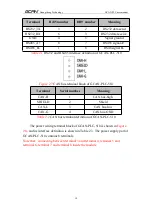
Page 10: ...s terminal block of GCAN PLC 510 Terminal Serial number Meaning CAN H 1 CAN bus high SHIELD 2 Shield CAN L 3 CAN bus low CAN G 4 CAN bus GND Table 2 2 CAN bus terminal definition of GCAN PLC 510 The p...

Page 11: ...er 4 IO positive power 5 IO negative power 6 IO negative power PE 7 shield PE 8 shield Table 2 3 GCAN PLC 510 terminal definition 2 5 System status indicator GCAN PLC 510 has two sets of status indica...

Page 12: ...lly not bright Power supply abnormally SYS Blinking Working status not bright Initialization error RUN Blinking Run normal not bright stop ERR bright System error not bright System normal IO RUN Blink...

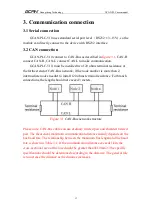
Page 13: ...more than 2 intermediate nodes needn t to install 120 ohms terminal resistance For branch connections the length should not exceed 3 meters Figure 3 1 CAN Bus network structure Please note CAN bus ca...

Page 14: ...shown in Figure 3 2 The value of the terminal matching resistance is determined by the characteristic impedance of the transmission cable For example the characteristic impedance of the twisted pair...

Page 15: ...plate Micro USB interface which is the refresh interface of the kernel GCAN PLC programmable logic controller uses Micro USB data line as download line of PLC core files You can connect GCAN PLC to US...

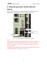
Page 16: ...gure 4 1 Physical picture after opening cover plate Note 1 When the dip switch of the running switch is up facing away from the reset button the PLC is in operation state When the dip switch of the ru...

Page 17: ...1_1086 html 5 2 Programming interface Figure 5 1 OpenPCS programming interface Programming interface of OpenPCS mainly contains 1 Menu 2 Project window 3 Edit window 4 Output window 5 Catalog window 5...

Page 18: ...a new file as shown in Figure 5 2 Figure 5 2 Create project 5 3 2 Add program page file Add files to the project for example add a program page ST Program written in ST language as shown in Figure 5...

Page 19: ...VAR v1 INT 0 v2 INT 0 oled at Q0 0 Byte END_VAR After the variable is defined start programming The following is a simple routine statement written in ST LED Marquee routines IF v1 100 then v1 v1 1 EL...

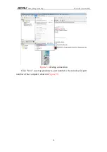
Page 20: ...20 Guangcheng Technology GCAN PLC user manual Figure 5 4 Debug connection Click New to set up parameters port number is the actual serial port number of the computer shown in Figure 5 5...

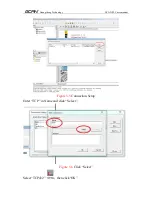
Page 21: ...Guangcheng Technology GCAN PLC user manual Figure 5 5 Connection Setup Enter TCP in Name and click Select Figure 5 6 Click Select Select TCP432 then click OK...

Page 22: ...Guangcheng Technology GCAN PLC user manual Figure 5 7 Select TCP432 Click Settings Figure 5 8 Click Settings Please enter 23042 for Port IP address 192 168 1 30 set the back point OK...

Page 23: ...Guangcheng Technology GCAN PLC user manual Figure 5 9 IP Address and Port Number Settings After completing the settings click Close Figure 5 10 Click Close Set Resource Properties...

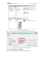
Page 24: ...manual Figure 5 11 Set Resource Properties Select GCAN_PLC and TCP then click OK to complete the setting Figure 5 12 Select GCAN_PLC and TCP 5 3 5 Download the program and debug After completing the...

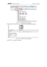
Page 25: ...heng Technology GCAN PLC user manual Figure 5 13 Completing the program Please check if there is an error warning after completing theprogram Figure 5 14 Check error and warning Click PLC then select...

Page 26: ...Guangcheng Technology GCAN PLC user manual Figure 5 15 Select Online Click PV PLC Download to download program Figure 5 16 Program download...

Page 27: ...2CAN Digital input GC 1008 Digital input PNP 24V DC 8 channel GC 1018 Digital input NPN 24V DC 8 channel GC 1502 Counter 200kHz max 2 channel Digital output GC 2008 Digital output PNP 24V DC 8 channe...

Page 28: ...t 16 bits 10V 10V 2 channel GC 4642 Current output 16 bits 0 20mA 2 channel GC 4652 Current output 16 bits 4 20mA 2 channel GC 4662 Voltage output 16 bits 0 5V 2 channel GC 4672 Voltage output 16 bits...

Page 29: ...tend terminal quantity module Up to 32 modules Digital I O signal 256 input output Analog I O signal 64 input output Configuration mode automatic configuration Real time clock Built in Floating point...

Page 30: ...55024 2011 09 EN 55022 2011 12 Anti vibration impact resistance performance EN 60068 2 6 EN 60068 2 27 29 Anti electromagnetic interference radiation performance EN 61000 6 2 EN 61000 6 4 IP grade IP...

Page 31: ...manual Sales and service Shenyang Guangcheng Technology Co Ltd Address No 135 21 Changqing Street Hunnan Shenyang Liaoning China E mail sygckj gmail com Tel Whatsapp 86 13644001762 Skype live sygckj W...

Reviews: