


QRG-S1080-1000
Revision C
Quick Reference Guide
Page 16 of 22
Company Proprietary Information
Feb 22, 2016
Selection
Action
5.
Focus Speed
Specify the focus speed from 0 to 3.
Click on the
Store
button to save your selections and wait for the changes to take effect.
7.3
Alignment Controls
Click first on the
Center
button, and then click on the
Store
button to center the camera on the desired location. Or,
use the directional arrows to move the camera in the direction indicated, and then click on the
Store
button to save
the camera position.
Click on the
Clear
button to clear all position settings. Click on the
Store
button to save position changes. Click on the
Back
button to return to the
Camera Settings Screen
.
8.0
AUDIO
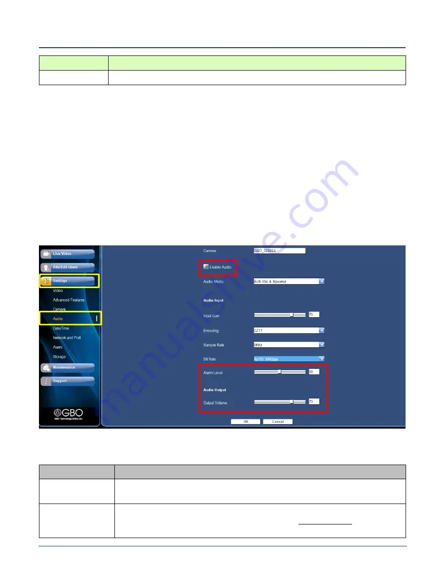
At the
Live Video Screen
(see Figure 15), click on
Settings
Audio
, and the
Audio
screen opens. At this screen you
can set advanced audio conditions. Only the primary settings are described in Table 4, below. Refer to the
S1080
User’s Manual
for more information on the parameters set at this screen.
Figure 23
Audio Setting Screen
Table 4
Audio Settings
Selection
Action
1.
Enable Audio
Click this checkbox to enable the functionality. The
Audio Mode
drop-down list opens.
Specify one of the following audio modes: MIC Only, Speaker Only, or MIC and Speaker.
2.
Alarm Level
Use the slider to specify the
Audio Level
that must be captured by the camera in order
to trigger an audio alarm. The
Enable Alarm
check box must be checked before the
alarm level can be set (see
Section 11.0, Alarm
).
All manuals and user guides at all-guides.com


