Click-Clak-Clak
Click-Clak
Click-Clak
(X”)
RECHARGE INSTRUCTION E ELECTRICAL WIRING
SYMBOLS LEGEND
The values by DEFAULT of the different parameters are underlined
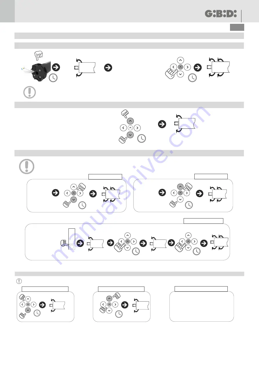
Push the button Prog on motor
header
REMOTE CONTROL OPERATION
Ascent
Stop
Descent
Programming
PUSHING TIME
Push the button for X seconds
TRANSMITTER STATUS
Transmitter already stored
OPERATION CONFIRMATION
P
N
New transmitter not stored
P2
Intermediate limit
switch
Transmitter to be cancelled
E
2”
RUNNER REB-B
4
UK
INSTALLATION
Ÿ
Ÿ
Ÿ
Ÿ
Ÿ
Ÿ
Ÿ
Put the adapter crown (5) on the base crown of the limit switch (7), being sure that the two reference joints (12 and 13) match.
Put the driving pulley (2) on the output pinion (3).
After putting the driving pulley on the output pinion, block it with the clip (1).
Put the square pin (9) in the square hole of limit switch header.
Put the iron plate (10) in the square pin (9) and fix it with the two closing screws (11).
Put the motor (4) in the roller tube (16), paying attention that the slot (14) of the driving pulley matches the roller tube slot (15).
Push the motor as long as the adapter crown (5) fits in the roller tube (16).
Parts to be read
carefully.
Ÿ
The motor includes a 12V lithium battery with charging station.
Ÿ
The motor does not need any fixed electrical wiring to the power supply, being provided with a lithium battery.
Ÿ
Max. charging capability: 12.6V-1A (Type C) and 12V-16V (Solar).
Ÿ
Before the first use, connect the power supply connector (panel / power adapter) to the motor and charge the battery for at least 6 hours.
Ÿ
During the operation, the motor will stop when the battery is less than 8V.
Ÿ
During the charging, the alarm will stop sounding when the battery is higher than 7V and will start souding again when it is lower than 7,5V.
Ÿ
When the motor is working with a 10V battery, the alarm will soud 10 times.
Jack charger
Solar panel
5
RUNNER REB-B
UK
1 - Storage of the first transmitter
2 - Modification of the rotation direction
3 - Manual storage of the limit switch
2”
Click-Clak
2”
Put the roller
shutter / curtain
at the lower limit
switch
proceed within 10 s, after
pushing the button Prog
Click-Clak
2”
Click-Clak
START UP:
Warning: during the positioning, the transmitter actions with buttons of Ascent and Descent direction hold-to-run: any time you push a button (ascent or
descent), the motor moves for 1 sec. Holding down the button for more than 2 s, the motor automatically moves.
Warning: next actions of the curtain / roller shutter must be carried out hold-to-run (operation par. 5).
If the ascent and descent buttons of the transmitter stored are right, proceed to par. 3, on the contrary to par. 2.
Put the roller
shutter / curtain at
lower limit switch
at the intermediate
position required
Click-Clak
Click-Clak
P2
1”
1”
Click-Clak
1”
1”
descent limit switch
ascent limit switch
intermediate limit switch
Put the roller
shutter / curtain
at the upper
limit switch
2”
Click-Clak
Click-Clak
2”
It is possible to remove either one limit switch or all of them. The procedure can be carried out with the roller shutter
in any position.
/ curtain
Click-Clak
5”
4 - Limit switch removal
Click-Clak
5”
5b - Remove ascent limit switch
5a - Remove descent limit switch
5c - Remove intermediate limit switch
Follow the same procedure
indicated in "INTERMEDIATE LIMIT
SWITCH" in chapter 3a


