background image


9


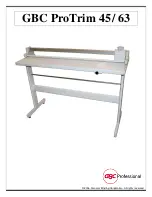
The GBC ProTrim 45 and 
ProTrim 63 were designed with 
ease of operation in mind.  
 
The steps for proper operation 
are as follows: 
  
1.) Move the cutter head all the 
way to the right or left side of 
the trimmer. (This is required 
because the paper clamp 
applies slight pressure to the 
print when the cutter head is 
not all the way to one side of 
the unit.)   
 
2.) Insert the print to be 
trimmed. 
  
3.) Adjust the edge guide as 
necessary to aid in squaring the 
print.  
 
4.) Use the paper clamp as an 
aid to determine where the cut 
will be made in the print. 
Support the print with one 
hand; use your other hand to 
slide the cutter head across the 
trimmer to make the cut.  
 
5.) Remove the trimmed pieces 
from the waste curtain as 
necessary.  


 Operation  

©2006. General Binding Corporation. All rights


reserved


Summary of Contents for ProTrim 45

Page 1: ...GBC ProTrim 45 63 2006 General Binding Corporation All rights reserved...

Page 2: ...x L Box ProTrim 45 12 5 x 23 75 x 59 ProTrim 63 12 5 x 23 75 x 76 5 Unit ProTrim 45 43 25 x 15 75 x 57 ProTrim 63 43 25 x 15 75 x 78 75 Cutting Specifications Maximum Cut Length ProTrim 45 45 ProTrim...

Page 3: ...r Distinguishable by rounded edges B Upper cross member Distinguishable by squared edges C Hardware Pack D Legs Left Right E Waste Curtain F Trimmer assembly Included Parts and Tools 2006 General Bind...

Page 4: ...to secure waste curtain shaft to stand C Bolts Qty 4 Used to secure the mid cross member to the legs D Bolts Qty 4 Used to secure the trimmer assembly to the stand E Hex Tool Includes one of the foll...

Page 5: ...per cross member on the floor then align one of the legs with the end of the cross member so the bolts can be inserted through the leg and into the upper cross member Use the bolts identified as A in...

Page 6: ...ex tool for these bolts The stand should now be completed Two people are required for the next step With one person on each side of the trimmer assembly carefully pick it up while keeping it level to...

Page 7: ...trimmer assembly to the top of the stand Use the 6mm Hex tool for these bolts Remove the wire ties from the waste curtain and then install the waste curtain in the rear of the trimmer as shown in the...

Page 8: ...er waste curtain support bar to the stand of the trimmer with the bolts identified as B earlier in this manual The assembly of the trimmer is now complete Assembly 2006 General Binding Corporation All...

Page 9: ...n the cutter head is not all the way to one side of the unit 2 Insert the print to be trimmed 3 Adjust the edge guide as necessary to aid in squaring the print 4 Use the paper clamp as an aid to deter...

Page 10: ...10 2006 General Binding Corporation All rights reserved...

Reviews: