background image

Page 7-1

ProCut 20P – Installation and Operating Instructions

7. o

Perator

 M

aIntenance

c

arInG


For


the

 P

ro

c

ut

 20P

The only maintenance required by the operator is to 

perform what is described in this section. Perform 

only 

the routine maintenance procedures referred to 

in these instructions. 


WARNINGS: 

• 

Before performing maintenance on the machine, 

turn the Circuit Breaker and Switch to OFF.*

• 

Do not attempt to repair the machine. Refer 

service to qualified service personnel.

• 

Do not lift, tilt, or attempt to move the machine. 

You can be severely injured or crushed.

Failure to observe these warnings could result in 

severe personal injury or death.

*If rotating or replacing the Cut Stick, see the 

instructions, shown below, before turning the 

machine OFF.

CAUTIONS:


•  Do not place materials on the table or near the 

Cutting Blade other than paper.

•  Do not cut through metal objects such as paper 

clips or staples.

• 

Do not allow foreign objects to fall into the working 

area of the machine. 

Failure to observe these cautions could result in 

damage to the machine.

c

leanInG

 t

he

 P

aPer

 c

utter

At the end of the day or project, clean up all waste 

and extra scraps off the working table. 

c

ut

 s

tIck

 r

otatIon


and

 r

ePlaceMent

The Cut Stick provides a clean cut as the Cutting 

Blade makes contact with it. When the Cut Stick is 

badly abraded and the paper is not cut cleanly, either 

rotate or replace the Cut Stick. The Cut Stick can be 

rotated to provide eight cutting surfaces. 

1.  Turn the Circuit Breaker and Switch to 

OFF

.

2. 

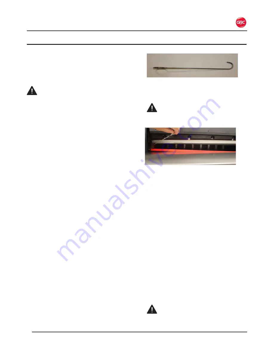
Insert the Stick Removal Tool into the end of the 

Cut Stick and pull up. 

Figure 19.  Cut Stick Removal Tool

3. 

From the front of the machine, lift the Cut Stick 

out of the groove.

WARNING: 

Keep fingers and hands clear of 

the Cutting Blade. Failure to observe these 

warnings could result in severe personal injury.

Figure 20.  Cut Stick Removal

4. 

Do one of the following:

•  Rotate the Cut Stick

•  Turn the Cut Stick end-to-end

• 

Replace the Cut Stick if all eight surfaces 

are abraded.

5. 

Put the Cut Stick back into the groove of the 

machine, making sure that both ends are level 

with the Working Table.

6.  With the machine powered ON, press the 

Reset


button.

•  The Cutting Blade and Clamp move to home 

position.

B

lade

 r

ePlaceMent

The Cutting Blade can be sharpened for re-use 

or replacement. The blade should be sharpened 

professionally. It will need to be sharpened or 

replaced under any of the following conditions.

•  Media is cut poorly

•  Cutting sounds abnormal

• 

After approximately 2,000 cuts

CALL YOUR LOCAL SERVICE TECH OR DEALER 

FOR BLADE REMOVAL OR SHARPENING.

 WARNING: Do not attempt to service the 

Cutting Blade. Failure to observe these warnings 

could result in severe personal injury.

Summary of Contents for ProCut 20P

Page 1: ...aper Cutter Model 20P INSTALLATION OPERATION MANUAL Document Number 1729247 Rev A Do not duplicate without written permission from ACCO Brands Store this instruction manual in a safe place for future reference ...

Page 2: ...1 Bramalea Road Mississauga ON L5S1C4 800 263 1063 www gbccanada com ACCO Mexicana Neptuno 43 Fraccionamien to Nueva Industrial Vallejo México 07700 D F Delagación Gustavo A Madero 55 1500 5778 www accomexico mx ACCO Brands 4 Corporate Drive Lake Zurich IL 60047 In USA call 800 772 9281 www gbcconnect com Introduction The equipment is designed to provide you with improved productivity versatility ...

Page 3: ...rior to Installation 4 1 Installation 4 1 Location 4 2 5 Feature Guide Infrared Safety Walls 5 1 Jogging Aid 5 1 Back Gauge 5 1 The Clamp Cutting Blade 5 1 Cut Stick 5 1 Control Panel 5 2 A LCD Display 5 2 B Keypad 5 2 C Operation Buttons 5 3 E Blade Adjustment 5 3 6 Operation Powering Up the Machine 6 1 Operating the Machine 6 1 Manual Operation 6 1 Programming the Machine 6 1 Entering a Program ...

Page 4: ...ProCut 20P Installation and Operating Instructions Page iii ...

Page 5: ... to you or others This safety alert symbol indicates a potential electrical shock It warns you not to open the machine and expose yourself to hazardous voltage The following warnings are found on the equipment WARNINGS Do not attempt to service or repair the machine Do not open the machine There are no serviceable parts inside Refer service to qualified service personnel Do not attempt to modify t...

Page 6: ...al The machine should be connected only to a source of power as indicated in these instructions and on the nomenclature plate located on the side of the machine Contact an electrician should the attachment plug provided not match the receptacles at your location After plugging in check that the power cord does not create a tripping hazard WARNING Do not attempt to service or repair Failure to obse...

Page 7: ...tors across even surfaces For warranty execution please contact ACCO Brands at 800 723 4000 or www gbcconnect com in the USA 800 263 1063 or www gbccanada com in Canada 55 1500 5578 or www accomexico mx in Mexico TO THE EXTENT ALLOWED BY APPLICABLE LAW THIS WARRANTY IS IN LIEU OF ALL OTHER EXPRESSED WARRANTIES REPRESENTATIONS OR PROMISES INCONSISTENT WITH OR IN ADDITION TO THIS WARRANTY ARE UNAUTH...

Page 8: ...ProCut 20P Installation and Operating Instructions Page 2 2 ...

Page 9: ...519 mm Dimensions Width Height Depth Work Table Height 34 5 in 876 mm 52 5 in 1334 mm 45 5 in 1156 mm 39 5 in 1003 mm Weight 419 lbs 190 kg Electrical Requirements Voltage Current Power Receptacle 208 240V 60 Hz 8A 1400 Watts NEMA 6 15P Cycle Time Operating time 7 seconds Rest time 3 seconds Paper Press Method Clamp Automatic Paper Pusher Back Gauge Automatic 3 Specifications W idth Depth Height F...

Page 10: ...ergy and if not installed and used in accordance with the instruction manual may cause harmful interference to radio communications Operation of this equipment in a residential area is likely to cause harmful interference in which case the user will be required to correct the interference at his own expense Canada Class A Notice Avis Canada Classe A This Class A digital apparatus complies with Can...

Page 11: ...ross anything other than a flat level surface without trained and qualified riggers You can be severely injured or crushed The ProCut 20P Series Cutter is a large and heavy piece of equipment It is not designed to be tipped up or tipped sideways in anyway Prepare the site 1 Allow enough room to access all sides of the machine Refer to the illustration on the next page 2 Ensure the floor is stable ...

Page 12: ...es behind the machine It is recommended that a media table be used to stage the sheets to be cut A second media table is recommended for finished material Keep the working area of the cutter free from clutter Avoid locating the cutter in a high traffic area When not in use the ProCut 20P can be unplugged Operator Media Table Media Table 6 inches 12 inches Figure 2 ProCut 20P Location ...

Page 13: ...ing the Jogging Aid to ensure a straight and accurate cut Laser Cut Line Figure 6 Red LED Laser Cut Line The cut line as shown in the photo above is visible only when the machine is turned ON The line indicates where the paper stack will be cut The Clamp Cutting Blade Figure 7 The Clamp dark grey and Cutting Blade The Clamp activates first pressing and holding down the media to ensure a clean cut ...

Page 14: ...in Alarm Indicates whether the alarm buzzer is enabled or disabled Reblading Mode Used when changing the blade WARNING Blade removal should only be done by a GBC Technician Failure to observe this warning could result in severe personal injury Behind the Blade Cut value is measured from behind the blade to the Back Gauge In Front of the Blade Cut values are measured by the amount of media the Back...

Page 15: ...on to move the cut sheets out from under the clamp and blade This is a safety feature to keep your hands away from the clamp and blade 6 Clamp Press the Clamp and Clamp Cut buttons simultaneously to engage the Clamp 7 Cut Press the Cut and Clamp Cut buttons simultaneously to engage the Blade 1 2 3 5 6 7 4 D Circuit Breaker Figure 12 Circuit Breaker If the machine experiences an overload or short c...

Page 16: ...ProCut 20P Installation and Operating Instructions Page 5 4 ...

Page 17: ...ears on the LCD Press the yellow Reset Button to set the Cutting Blade to the HOME position and calibrate the Back Gauge by returning to the home position and returning to the last used numeric setting Place the media on the Working Table and use the Jogging Aid to push the leading edge against the Back Gauge and align the sheets Using both hands simultaneously press and hold the Clamp Cut and Cut...

Page 18: ... the machine to the home screen and auto setup for the first cut of your program The first step is highlighted You are now ready to begin your job 11 Make the first cut by simultaneously pressing the Clamp Cut and Cut buttons until it finishes cutting 01 10 00 00 00 00 00 00 00 00 00 00 00 6 00 8 00 05 06 02 07 03 08 04 01 Behind Blade program The Back Gauge then moves to the second step cut posit...

Page 19: ...t as the Cutting Blade makes contact with it When the Cut Stick is badly abraded and the paper is not cut cleanly either rotate or replace the Cut Stick The Cut Stick can be rotated to provide eight cutting surfaces 1 Turn the Circuit Breaker and Switch to OFF 2 Insert the Stick Removal Tool into the end of the Cut Stick and pull up Figure 19 Cut Stick Removal Tool 3 From the front of the machine ...

Page 20: ... be disassembled so its components and materials can be recycled re used and recovered burned for energy content in electricity production Public collection points have been set up by municipalities for the collection of WEEE free of charge to you Please return your WEEE to the collection facility nearest your home or office If you have difficulty locating a collection facility the retailer that s...

Page 21: ...rn on off the audio warning for the Safety Curtain You are turning off an audible warning for a safety feature use at your own discretion Reblading Mode Blade change mode OFF 01 00 00 00 00 00 00 00 00 00 00 00 00 00 00 00 00 05 06 02 07 03 08 04 Service mode used when replacing the blade CALL YOUR LOCAL SERVICE TECH OR DEALER FOR BLADE REMOVAL OR SHARPENING Reset Service adjustment to optimize pe...

Page 22: ...Function is highlighted on the LCD press the Enter button again The value is highlighted 01 00 00 00 00 00 00 00 00 00 00 00 00 00 00 00 00 05 06 02 07 03 08 04 00 Behind blade program Figure 22 Value to Change 3 Press the Up or Down arrow keys to change the value Each time the arrow key is pressed the changed value is displayed 4 Press Enter when your desired value is shown 01 12 50 00 00 00 00 0...

Page 23: ......

Page 24: ...ion 1729247 Rev A 2015 03 ACCO Brands Canada 5 Precidio Court Brampton ON L6S 6B7 800 263 1063 www gbccanada com ACCO Mexicana Neptuno 43 Colonia Nueva Industrial Vallejo Delagacion Gustavo A Madero CP 07700 México DF 55 1500 5578 www accomexico mx ACCO Brands 4 Corporate Drive Lake Zurich IL 60047 In USA call 800 772 9281 www gbcconnect com ...

Reviews: