


™
3
5
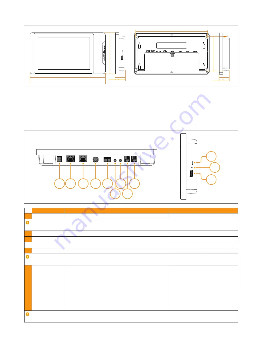
EL3 Controller Dimensions
6
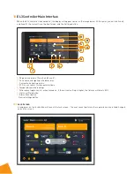
Connection Interface Introduction
A.
DC 15V 3A DC Power Adapter
B.
Zone B Dimming
C.
Zone A Dimming
D.
Sensor Digital Sensor
E.
ALARM
F.
T-B Zone B Temperature Sensor
250mm
238mm
33.6mm
12.2mm
137.4mm
114mm
21.4mm
33.6mm
12.2mm 21.4mm
A B C D E
F
G
H
I
J
L
K
G.
T-A Zone A Temperature Sensor
H.
Dry Contractor A&B
I.
0-11.5V Input A&B
J.
Debug Port
K.
Reset Key
L.
USB Port
NAME
DESCRIPTION
SPECIFICATION
A:
DC 15 V 3 A
DC Power Input
•
Attention:
The input voltage should be kept above 13V and below 18V DC; the input current should not be lower than
3A; otherwise, the product may not work properly.
B:
Zone B
Control the dimming of luminaires in Zone B
•
C:
Zone A
Control the dimming of luminaires in Zone A
•
Attention:
The original cable provided by the manufacturer must be used to connect to this port.
D:
Sensor
For compatible Titan Controls Sensors (sold separately)
•
Attention:
Do not connect the fixture to the sensor port. Use only for the sensor; otherwise, permanent damage
to the sensor and controller may occur.
E:
Alarm
Switching control of alarm
1)
Positive alarm equipment switch
signal line access point
2)
Positive alarm equipment switch
signal line access point
3)
Reverse alarm device switch signal
line access point
4)
Reverse alarm device switch signal
line access point
Attention:
The port output is a switching signal and does not have voltage/current drive capability. If voltage and current
are applied to the port, the nominal switching capacity should not exceed: 1A 30V DC, 0.3A 125V AC (resistive load).