background image

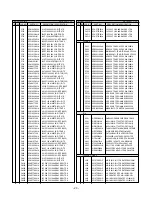
PRINTED CIRCUIT BOARD

- 18 -

J713

R830

C820

C817

U301

C301

U302

C302

U303

C318

C815

P/N  :6870T362A1

1

MODEL:LG883D

DA
TE :2001.07.15

C413

30

20

30

20

30

20

J801

C408

40

50

30

20

L403

10

10

10

ZD704

ZD703

C816

60

70

L401

10

L402

50

1

50

1

50

1

RA237

RA239

RA238

RA242

C819

U802

R810

C818

80

90

100

1

C410

RA225

RA226

RA214

RA227

RA229

RA228

RA230

RA231

RA233

RA232

RA235

RA234

RA236

RA240

RA241

D703

D704

R809

R805

C808

U401

CA201

CA202

RA216

Y

W

V

U

T

R

L212

C229

L211

D702

D701

C809

R804

C807

U801

R803

10

CA21

1

CA209

CA210

CA207

CA208

CA203

CA206

CA212

RA218

RA220

J

K

L

M

P

N

C230

R219

R218

X201

R235

J704

C712

C805

20

R801

R802

1

C804

CA204

CA205

RA224

RA222

C

D

E

F

G

H

C286

C282

C258

R221

C261

R225

C284

C283

R551

R231

ZD702

Q701

R706

C71

1

Q702

R707

C803

ZD806

RA212

C409

RA210

RA208

RA204

RA206

RA202

U201

20

14

15

16

17

18

19

8

9

10

11

12

13

2345

6

7

1

A

B

C288

C287

C281

R220

R222

C280

C260

C259

R224

R223

C285

R550

R549

R548

R229

R227

C730

ZD701

C732

R406

C834

R545

20

C201

C204

C203

C202

C205

C206

D714

D713

C801

L801

R544

R543

R532

C516

C517

R542

R508

C831

C828

L805

C731

U710

C524

D712

D711

C802

C707

U821

U502

30

R533

Q501

L804

C825

U503

D710

D708

D709

C710

L701

C701

R702

R701

C518

10

C502

X501

R502

U803

U820

D707

J708

D732

L703

L702

C706

40

C522

R501

C501

R825

R826

R827

R828

R823

R822

R821

R820

C822

L705

L707

L708

C525

ZD705

D503

D502

J702

C521

U501

1

C503

R829

R824

R733

L704

J711

1. MAIN BOARD (Component Side)

Summary of Contents for FPD1810

Page 1: ...AUTO SOURCE SET OSD COLOR MONITOR SERVICE MANUAL CAUTION BEFORE SERVICING THE UNIT READ THE SAFETY PRECAUTIONS IN THIS MANUAL MODEL FPD1810 CHASSIS NO CL 23 FACTORY MODEL LG883D ...

Page 2: ...requency Horizontal 31 81kHz Vertical 56 85Hz 4 POWER SUPPLY 4 1 Power Adaptor Input AC 100 240V 50 60H 1 2A Output DC 12V 5 8A 4 2 Power Consumption 5 ENVIRONMENT 5 1 Operating Temperature 0 C 35 C 32 F 95 F Ambient 5 2 Relative Humidity 10 80 Non condensing 5 3 MTBF 50 000 Hours Min 6 DIMENSIONS with TILT SWIVEL Width 449mm 17 6 Depth 205mm 8 1 Height 443mm 17 4 7 WEIGHT with TILT SWIVEL Net Wei...

Page 3: ... as pencil or pen as this may result in damage to the panel Protect the module from the ESD as it may damage the electronic circuit C MOS Make certain that treatment person s body are grounded through wrist band Do not leave the module in high temperature and in areas of high humidity for a long time The module not be exposed to the direct sunlight Avoid contact with water as it may a short circui...

Page 4: ...768 3 6 29 H 60 123 1312 1024 16 96 176 V 75 029 800 768 1 3 28 H 68 677 1376 1024 48 96 208 V 84 997 808 768 1 3 36 H 68 681 1456 1152 32 128 144 V 75 062 915 870 3 3 39 H 61 805 1504 1125 18 134 200 V 65 96 937 900 2 4 31 H 63 981 1688 1280 48 112 248 V 60 02 1066 1024 1 3 38 H 79 976 1688 1280 16 144 248 V 75 035 1066 1024 1 3 38 Mode H V Sort 1 2 3 4 5 6 7 8 9 10 11 12 13 14 15 16 25 175 28 32...

Page 5: ...hese buttons to choose or adjust items in the on screen display 4 SOURCE SET Button Use this button to make Dsub or DVI connector active This feature is used when two computers are connected to the monitor The default setting is Dsub Use this button to enter a selection in the on screen display 5 OSD Button Use this button to enter or exit the on screen display AUTO SOURCE SET OSD Buttons OSD Butt...

Page 6: ...J702 J711 J1 J713 CN3 CN2 ...

Page 7: ...bly 2 BACK COVER CONTROL PCB ASSEMBLY REMOVAL 1 Remove four screws a 2 Remove the Backcover assembly 3 Remove Backcover from the Coltrol PCB ass y 12 V a a a a a a a b b b a b a a J702 J711 J713 to Control PCB J1 3 MAIN TOTAL ASSEMBLY REMOVAL 1 Remove six screws a 2 Remove the Metal Rear 3 Disconnect J711 J713 and J702 4 Remove four screws b 5 Remove the Main PCB ass y Tip Spec a Width 5 0 9 0mm b...

Page 8: ...emove two Aluminium Tape a 2 Remove the LCD Module LCD Module a a b CN3 CN2 4 INVERTER ASSEMBLY REMOVAL 1 Remove two screws a 2 Remove Main Inverter shield ass y 3 Remove the screw b 4 Disvonnect CN2 CN3 5 Remove the Inverter ass y ...

Page 9: ... DE H V Sync out R G B Even LCD Module R G B differential LVDS Low Voltage Differential Signaling Data 48 Bit Address D SUB Inverter CTL Module CTL R G B even odd Inverter DC DC Conve rter Digital Signal 5V 3 3V Reg DVDD 3 3V AVD D 3 3V 12V Po wer CTL H V Sync ADC CLK 12V 12V AVDD 2 5V 2 5V Reg DVDD2 5V AVD D2 5V 3 3V Reg PVDD 3 3V 5V 5V ...

Page 10: ...75mm Gm5020 Video Scaler ADC TMDS Rx Memory Memory Memory LVDS DVI D D SUB Panel Link Cable Micom Control Pin DC DC Converter Inverter Pin Module Power Power Jack 150mm 120mm ...

Page 11: ... signal and outputs 8 bit R G B signal to transmitter Especially pre amp ADC Video controller are merged to one chip Gm5020 by Genesis Also FRC is separate 3 Display Data Transmitter Part This part transmit digital signal from the Scaler to the receiver of module 4 Power Part This part consists of the DC DC converter and two 3 3V and one 2 5 regulators The DC DC converter coverts 12V to be entered...

Page 12: ...Generator eg VG 819 made by Astrodesign Co E E PROM with each mode data saved Alignment Adapter and Software 1 Adjustment for Factory Preset Mode 1 Run alignment program for FPD1810 on the IBM compatible PC 2 Select EEPROM all clear command and Enter 3 Display cross hatch pattern at Mode 1 4 Select COMMAND PRESET START command 5 Select FOS DEFAULT command and Enter 6 Press Y key it will automatica...

Page 13: ...ER TROUBLE IN U801 CHECK 5VS VOLTAGE 5V NO NO POWER POWER INDICATOR OFF TROUBLE SOMEWHERE ELSE TROUBLE IN ADAPTOR or INVERTER CHECK U801 INPUT VOLTAGE 12V NO TROUBLE IN U501 or X501 NO YES YES YES CHECK U501 PIN 6 IS THIS PIN OSCILLATED ...

Page 14: ... NO NO RASTER TROUBLE IN POWER ADATER CHECK J702 PIN 10 12V NO TROUBLE IN X201 CHECK X201 H CLOCK NO TROUBLE IN U201 CHECK L201 GM5020 NO TROUBLE IN U201 NO TROUBLE IN U201 CHECK U301 U302 U303 PIN 35 MEMORYCLK NO YES YES YES YES YES YES CHECK L202 L203 H PULSE ...

Page 15: ... 15 CHECK DOT CLOCK PATTERN NO CHECK DVS PATTERN NO CHECK DHS PATTERN NO YES YES YES YES TROUBLE IN LCD MODULE CHECK U401 PIN 8 V PULSE CHECK U401 PIN 7 V PULSE CHECK U401 PIN 10 H CLOCK ...

Page 16: ... 16 3 NO CLOCK CLOCK GENERATOR NO DOT CLOCK TROUBLE IN X201 CHECK X201 24MHz NO TROUBLE IN U201 CHECK L201 CLOCK NO YES YES ...

Page 17: ...LE IN DPM TROUBLE IN DPM TROUBLE IN PC CHECK PC CPC IS NOT GOING INTP DPM OFF MODE NO TROUBLE IN X501 NO TROUBLE IN SIGNAL CABLE NO YES YES YES CHECK U501 PIN 6 WAVEFORM 24MHz CHECK R233 R234 CHECK U501 PIN 11 0V ...

Page 18: ...5 20 R801 R802 1 C804 CA204 CA205 RA224 RA222 C D E F G H C286 C282 C258 R221 C261 R225 C284 C283 R551 R231 ZD702 Q701 R706 C711 Q702 R707 C803 ZD806 RA212 C409 RA210 RA208 RA204 RA206 RA202 U201 20 14 15 16 17 18 19 8 9 10 11 12 13 2 3 4 5 6 7 1 A B C288 C287 C281 R220 R222 C280 C260 C259 R224 R223 C285 R550 R549 R548 R229 R227 C730 ZD701 C732 R406 C834 R545 20 C201 C204 C203 C202 C205 C206 D714 ...

Page 19: ...264 R233 R709 D730 D731 C813 C231 C232 L201 L202 C235 C234 C225 C233 R201 C222 C228 C227 C226 C276 C269 C273 C274 C271 C270 R708 C713 C727 R717 R710 C716 C812 C236 L203 L204 C238 R202 R242 R243 C237 R236 R237 R239 R240 R241 C275 C272 ZD706 C412 C411 C835 C836 R511 R512 C257 C514 C515 R524 R525 C507 D205 D206 D207 D208 D204 R238 D201 D202 R718 C728 R729 R728 R806 C810 R513 R537 C504 C505 C519 R527 ...

Page 20: ...EXPLODED VIEW 1 3 4 5 9 12 13 11 12 V 14 16 15 6 2 8 7 10 ...

Page 21: ...TFT COLOR 18 1 BACK COVER ASSEMBLY LG883D 3808TKL022A TILT SWIVEL ASSY LG883D METAL ASSY FRAME MAIN LG883D INVERTER ASSY SAMSUNG LG1805 LG883D METAL ASSEMBLY SHIELD INVERTER PWB PCB ASSEMBLY MAIN LG883D XAGC G WAY MAIN TOTAL CONNECTOR ASSEMBLY 31P H H 95MM UL20276 UNIXTAR LG883D METAL ASSEMBLY REAR LG883D PWB PCB ASSEMBLY SUB LG883D XAGC G WAY CONTROL TOTAL SCREW PVS 4 10 MSWR FZMW SCREW PZP 3 16 ...

Page 22: ... DATE 2001 7 30 S AL LOC NO PART NO DESCRIPTION SPECIFICATION C282 0CK103CK51A 0 01UF 1608 50V 10 R TP B Y5P C301 0CK103CK51A 0 01UF 1608 50V 10 R TP B Y5P C302 0CK103CK51A 0 01UF 1608 50V 10 R TP B Y5P C303 0CK103CK51A 0 01UF 1608 50V 10 R TP B Y5P C304 0CK103CK51A 0 01UF 1608 50V 10 R TP B Y5P C305 0CK103CK51A 0 01UF 1608 50V 10 R TP B Y5P C306 0CK103CK51A 0 01UF 1608 50V 10 R TP B Y5P C307 0CK1...

Page 23: ...K CA205 0CHZTTA001A 10F 50V F 3216 4ARRAY REEL TDK CA206 0CHZTTA001A 10F 50V F 3216 4ARRAY REEL TDK CA207 0CHZTTA001A 10F 50V F 3216 4ARRAY REEL TDK CA208 0CHZTTA001A 10F 50V F 3216 4ARRAY REEL TDK MODEL FPD1810 DATE 2001 7 30 S AL LOC NO PART NO DESCRIPTION SPECIFICATION CA209 0CHZTTA001A 10F 50V F 3216 4ARRAY REEL TDK CA210 0CHZTTA001A 10F 50V F 3216 4ARRAY REEL TDK CA211 0CHZTTA001A 10F 50V F 3...

Page 24: ... FPD1810 DATE 2001 7 30 S AL LOC NO PART NO DESCRIPTION SPECIFICATION R242 0RJ0000D677 0 OHM 1 10 W 5 1608 R TP R243 0RJ0000D677 0 OHM 1 10 W 5 1608 R TP R401 0RJ1002D677 10K OHM 1 10 W 5 1608 R TP R402 0RJ1002D677 10K OHM 1 10 W 5 1608 R TP R403 0RJ1002D677 10K OHM 1 10 W 5 1608 R TP R404 0RJ1002D677 10K OHM 1 10 W 5 1608 R TP R406 0RJ0000D677 0 OHM 1 10 W 5 1608 R TP R501 0RJ1004D677 1000000 OHM...

Page 25: ...RA228 0RHZTCZ001D 22 OHM 1 16 W 5 3215 R TP RA229 0RHZTCZ001D 22 OHM 1 16 W 5 3215 R TP RA230 0RHZTCZ001D 22 OHM 1 16 W 5 3215 R TP RA231 0RHZTCZ001D 22 OHM 1 16 W 5 3215 R TP RA232 0RHZTCZ001D 22 OHM 1 16 W 5 3215 R TP RA233 0RHZTCZ001D 22 OHM 1 16 W 5 3215 R TP RA234 0RHZTCZ001D 22 OHM 1 16 W 5 3215 R TP RA235 0RHZTCZ001D 22 OHM 1 16 W 5 3215 R TP RA236 0RHZTCZ001D 22 OHM 1 16 W 5 3215 R TP RA23...

Page 26: ...12 13 11 19 10 20 BOOT INH D94IN163A SO20 Pin Configuration L4973V3 L4973V5 L4973D3 L4973D5 VREF GOOD 5 1V COMP VFB SYNC BOOT DRIVER HICCUP CURRENT LIMITING INTERNAL REFERENCE SS INH ZERO CURRENT INHIBIT D94IN161B 3 3V V5 1 E A SOFT START 5 1V 3 3V THERMAL SHUTDOWN INTERNAL SUPPLY 5 1V PWM CURRENT LIMITING R S Q Q CBOOT CHARGE OSCILLATOR OUT OUT2 GND OSC VCC2 VCC 17 19 11 12 12 13 18 20 1 1 2 2 3 ...

Page 27: ... VSS VDD3 21 PTE0 SOG TCH0 PD1 D PD0 D PTA1 PWM9 PTA0 PWM8 PTA2 PWM10 PTD6 IICSDA PTD5 IICSCL PTD3 DDCSCL VSS1 PTD2 DDCSDA HSYNC PTB3 PWM3 PTB4 PWM4 40 39 38 37 36 35 34 33 32 31 30 29 28 27 26 25 24 23 22 41 PTB0 PWM0 PTB1 PWM1 PTB2 PWM2 42 PTD4 CLAMP PTC2 ADC2 PTC1 ADC1 PTC0 ADC0 PTE1 HSYNO PTE2 VSYNO PTC3 ADC3 42 PIN SDIP 5V open drain MC68HC908BD48 3 3V port else 5V port MC68HC908BD ...

Page 28: ... 28 PARTS TYPE PARTS TYPE BA033FP 1 Vcc 2 GND 3 OUT 1 3 2 ICs Transistor KIA7042F 1 3 2 1 Vcc 2 GND 3 OUT ...

Page 29: ...1 VIDEO PROCESS ...

Page 30: ...2 MEMORY ...

Page 31: ...3 LVDS ...

Page 32: ...4 MICOM ...

Page 33: ...5 POWER GEN ...

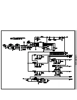
Page 34: ...6 CONNECTOR JACK ...

Reviews: