background image

20

Chapter 2: Setting Up Your Server

www.gateway.com

Starting your server

Before you start your server for the first time:

Make sure that the server and monitor are plugged into a power outlet or 
surge protector and that the surge protector (if you are using one) is turned 
on.

Make sure that all cables are connected securely to the correct ports and 
jacks on the back of the server.

To start the server:

1

Turn on any peripheral devices connected to the server.

2

Press the power button.

Warning

When you connect peripheral devices to the server, make 
sure that your server and devices are turned off and the 
power cords are unplugged.
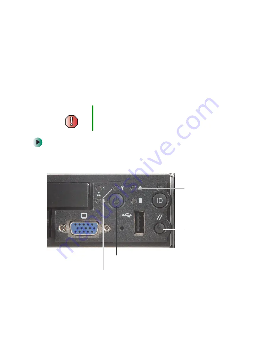
Power indicator

Power button

System fault 
indicator

Reset button

Summary of Contents for 955

Page 1: ......

Page 2: ......

Page 3: ...net 19 Starting your server 20 Understanding the power on self test 22 Turning off your server 22 Setting up the operating system 23 3 Maintaining Your Server 25 Caring for your server 26 Cleaning your server 26 Preparing for system recovery 28 Recording the BIOS configuration 28 System administration 29 Gateway Server Manager 29 Server security 29 Using your Server Companion CD 31 Identifying you...

Page 4: ...lacing the fan module 64 Installing a processor 67 Replacing the power supply 71 Replacing the SCSI backplane 74 Replacing the CMOS battery 77 Replacing the power distribution board 79 Replacing the front panel board 81 Replacing the system board 84 5 Using the BIOS Setup Utility 89 Opening the BIOS Setup utility 90 Updating the BIOS 91 Resetting the BIOS 92 Resetting BIOS passwords 93 6 Troublesh...

Page 5: ...108 Modem telephone dial up 108 Monitor 110 Power 111 Processor 111 A Server Specifications 113 System specifications 114 System board specifications 115 Environmental specifications 116 Additional specifications 117 B BIOS Settings 119 C Safety Regulatory and Legal Information 125 Index 133 ...

Page 6: ...iv ...

Page 7: ...1 1 Checking Out Your Gateway Server Read this chapter to learn Where drives ports jacks and controls are located Where system board components are located What help resources are available ...

Page 8: ...drive 1 CD drive Diskette drive Control panel SCSI hard drive 2 System fault indicator Hard drive activity indicator VGA port LAN 1 activity indicator Power indicator LAN 2 activity indicator Power button USB port Reset button System ID button System ID indicator Non maskable interrupt button ...

Page 9: ... gateway com Back LAN 2 jack Serial RJ 45 port Low profile PCI expansion Power connector External SCSI PS 2 mouse keyboard port USB port Full height PCI expansion LAN 1 jack VGA port USB port System ID indicator ...

Page 10: ...erver www gateway com Interior Low profile riser card Flex bay Full height riser card I O ports Power supply Memory slots Processor 1 Fan module Processor 2 Hot swap SCSI hard drives Front panel board Power distribution board SCSI backplane ...

Page 11: ... System board www gateway com System board Connectors Auxiliary power Fan module power Auxiliary signal Diskette IDE Main power Front panel USB PCI riser card low profile PCI riser card full height SCSI ...

Page 12: ... For more information see Using Your Server Companion CD Gateway Web site Gateway provides a variety of information on its Web site to help you use your server Visit the Gateway Web site at support gateway com for Technical documentation and product guides Technical tips and support Updated hardware drivers Order status Frequently asked questions FAQs Telephone support You can access a wide range ...

Page 13: ...2 7 Setting Up Your Server Read this chapter to learn how to Use your server safely Install your server into a cabinet Start and turn off your server Set up your operating system ...

Page 14: ...or other heat generating objects Damage caused by extreme temperatures is not covered by your warranty As a general rule your server is safest at temperatures that are comfortable for you Keep your server and magnetic media away from equipment that generates magnetic fields such as unshielded stereo speakers Strong magnetic fields can erase data on both diskettes and hard drives Even a telephone p...

Page 15: ...ertification for your location such as Underwriters Laboratories UL Check the maximum amount of voltage the protector allows to pass through the line The lower the voltage that the protector allows to pass through the better the protection for your server Check the energy absorption dissipation rating The higher the energy absorption rating the better the protection for your server Check for line ...

Page 16: ...rcuit with a device that causes electromagnetic interference such as a television or a motor Some surge protectors and uninterruptible power supplies include simple line conditioning capabilities Uninterruptible power supplies Use an uninterruptible power supply UPS to protect your server from data loss during a total power failure A UPS uses a battery to keep your server running temporarily durin...

Page 17: ...rdware from the cabinet manufacturer Rackmount kit contents Server rails 2 Cabinet rails 2 L brackets 2 not used for this type of installation Fastener pack 1 Small screws 4 6 32 3 16 inch Medium screws 8 10 32 inch Large screws 2 10 32 7 8 inch Handle spacers 2 Nut bars 4 Disk guides 2 Warning Before attaching cabinet accessories make sure that the server is turned off and all power cords are unp...

Page 18: ...from each handle then set the handles and screws aside 2 Align the holes in a server rail with the tabs on the side of the server then place the rail against the server and slide the rail as far forward as it will go Both server rails are identical so you can use either rail on either side of the server Screws ...

Page 19: ...www gateway com 3 Use one of the small screws to fasten the rail to the server then attach the remaining rail to the other side of the server 4 Place a disk guide over the disk guide screw hole towards the back of the server Screw Screw hole ...

Page 20: ...e and tighten the screw Attach the remaining disk guide to the other side of the server 6 Attach a nut bar to the inside of the two rear cabinet posts using medium screws but do not completely tighten the screws leave them loose enough to allow insertion of the cabinet rail in the next step Screw ...

Page 21: ...erver insert it into the cabinet from the front then position the disk guides so they fit in the cabinet rails 9 Push the server toward the back of the cabinet until the front of the server rails touch the front cabinet posts Warning Lifting the server and attaching it to the rack is a two person job If needed use an appropriate lifting device A fully loaded Gateway 955 server weighs about 30 lbs ...

Page 22: ...et post using two of the medium screws and one nut bar then attach the remaining rail to the other cabinet post Warning Screws are required to support the front of the server You must support the server while installing or removing the front screws and while sliding the server on or off the cabinet rails ...

Page 23: ...the front screw hole on the handle then insert a spacer onto the part of the screw protruding from the back of the handle 2 Slide a handle with its attached screw and spacer between the server and the server rail Important The front cover is held in place by the server handles If you are not installing the front cover you do not need to install the handles ...

Page 24: ... Align the screw on the handle with the center hole in the server rail then tighten the screw 4 Attach the remaining handle to the other side of the server 5 Remove the front cover lock keys from the inside of the front cover then snap on the front cover ...

Page 25: ... front cover if installed 2 Remove the handles if installed 3 While supporting the front of the server remove the four screws that secure the server rails to the front cabinet posts 4 While supporting the server slide the server away from the cabinet until it slides off the cabinet rails Warning Screws are required to support the front of the server You must support the server while removing the f...

Page 26: ... are using one is turned on Make sure that all cables are connected securely to the correct ports and jacks on the back of the server To start the server 1 Turn on any peripheral devices connected to the server 2 Press the power button Warning When you connect peripheral devices to the server make sure that your server and devices are turned off and the power cords are unplugged Power indicator Po...

Page 27: ...ng Help on page 6 3 The first time you turn on the server any pre installed operating system may begin asking you for configuration settings See your operating system s documentation for instructions on configuring advanced settings for your specific network When the power indicator is It means Green steady on The server is turned on Green blinking The server is in sleep mode Off The server is tur...

Page 28: ... system You may lose data if you do not follow the correct procedure To turn off the server 1 See the operating system s documentation or online help for instructions on shutting down the operating system Whenever possible you should use the operating system s shut down procedure instead of pressing the power button 2 If your server did not turn off automatically press the power button OR Press th...

Page 29: ...led by Gateway it is completely installed and the basic settings are already configured See your operating system s documentation for instructions on configuring advanced settings for your specific network If you are installing an operating system because it was not already installed by Gateway see the appropriate installation guide for instructions ...

Page 30: ...24 Chapter 2 Setting Up Your Server www gateway com ...

Page 31: ...3 25 Maintaining Your Server Read this chapter to learn how to Care for your server Record the BIOS configuration Manage your server and network ...

Page 32: ...es is not covered by your warranty As a general rule your server is safest at temperatures that are comfortable for you Keep all liquids away from your server When spilled onto server components almost any liquid can result in extremely expensive repairs that are not covered under your warranty Avoid dusty or dirty work environments Dust and dirt can clog the internal mechanisms and can cause the ...

Page 33: ...the keyboard upside down to let the liquid drain Let the keyboard dry completely before trying to use it again If the keyboard does not work after it dries you may need to replace it Keyboard damage resulting from spilled liquids is not covered by your warranty Cleaning the screen If your computer screen is a flat panel display use only a damp soft cloth to clean it Never spray water directly onto...

Page 34: ... diskette to back up critical operating system files See your operating system s documentation or online help for instructions on creating and using an emergency repair diskette Recording the BIOS configuration To help keep track of your custom changes to BIOS settings and to prepare for system recovery you should record your BIOS configuration after you have your server set up and working To reco...

Page 35: ...y certain events or conditions Printed documentation comes with the Gateway Server Manager CD You can find additional documentation in the program s online help Server security Locking the server To lock the server 1 Remove the front cover lock keys from the inside of the front cover then snap on the front cover The handles must be installed for the cover to snap on For instructions see Installing...

Page 36: ...lity opens 2 Select the Security menu 3 Select Administrator Password 4 Type the password and press ENTER then type it again and press ENTER 5 Save your changes and close the BIOS Setup utility To remove a BIOS security password 1 Restart your server then press F2 when the Gateway logo screen appears during startup The BIOS Setup utility opens 2 Select the Security menu then select the password to...

Page 37: ...D www gateway com Using your Server Companion CD You can use your Server Companion CD to Install hardware drivers Install programs View server documentation Instructions for using the CD are provided in Using Your Server Companion CD ...

Page 38: ... blue LED that you can turn on to help you locate the correct server Your server has a System ID indicator in the front and in the back To turn on the System ID indicator 1 Press the System ID button The two blue System ID indicators turn on For the System ID indicator to turn on the server does not need to be turned on but it does need to be plugged in 2 To turn off the indicator press the System...

Page 39: ...itoring server components and sensors Managing nonvolatile storage for the system event log and sensor data records Interfacing with the emergency management port RJ 45 serial on back panel and LAN 1 port to send alerts and interact with remote management systems Providing the main front panel controls such as power and reset You should update the BMC firmware when Gateway Technical Support has in...

Page 40: ...til the Standby power LED turns off 2 Follow the instructions in Opening the server case on page 46 3 Move the BMC Write Enable jumper to pins 1 2 4 Follow the instructions in Closing the server case on page 48 then reconnect the power cord 5 Create a DOS bootable diskette Caution If you do not disconnect the power cord when instructed to in this procedure the BMC firmware will not update Pins 1 2...

Page 41: ...ns included with the update file 8 Turn off the server then disconnect the power cord and wait for the Standby power LED to turn off 9 Follow the instructions in Opening the server case on page 46 10 Move the BMC Write Enable jumper back to pins 2 3 11 Follow the instructions in Closing the server case on page 48 then reconnect the power cord Pins 2 3 ...

Page 42: ...it FRU information 1 Boot your server from the Server Companion CD then select System Setup Utility from the menu The System Setup Utility starts 2 From the SSU Main window click FRU Manager The SSU automatically loads the current list of events from non volatile memory 3 Click the category for Chassis Board or Product The category expands to show a list of components for that category 4 Click a c...

Page 43: ...erver so that you can perform system management tasks remotely Setting up remote LAN access To set up remote LAN access 1 Boot your server from the Server Companion CD then select System Setup Utility from the menu The System Setup Utility starts 2 In the SSU Main window click Platform Event Manager PEM 3 In the PEM window click Configure LAN 4 To require a password for remote access type the pass...

Page 44: ...boxes in the dialog box are ignored Static Assign the IP address for the server using the Host Gateway and Subnet Mask boxes in the dialog box 7 If you selected Static in the previous step complete the IP addressing boxes Host IP Address The IP address of this server Gateway IP Address The IP address of the router for this server Subnet Mask The IP address for the server s subnet The server uses t...

Page 45: ...her access modes 6 In the System Phone Number box type the number for the phone line connected to the modem on the EMP 7 In the Access Mode list click the remote access mode Always Active The EMP is available at any time Preboot The EMP is available only when the server is powered down or is running POST during startup After the operating system is loaded a connection cannot be made Disabled Remot...

Page 46: ...on The EMP automatically sends an ENTER character following this string The maximum length for the string is eight characters Modem Dial Command The command to dial a phone number This string is sent to the modem before sending the paging string Modem Init String Initialization string for the modem Sent every time the EMP initializes You will be notified if the string is truncated Following a save...

Page 47: ...abled list to the Disabled list Moves the selected event from the Enabled list to the Disabled list Moves the selected event from the Disabled list to the Enabled list Moves all events from the Disabled list to the Enabled list 14 Click Save to save the changes 15 Click Close to return to the PEP Configuration window 16 To send a test page to verify that you have correctly configured PEP click Opt...

Page 48: ...Subnet Mask The IP address for the server s subnet The server uses this to decide if the alert destination is on the same subnet 8 In the Alert IP Address box complete the IP address of the system you want to receive alerts from this server If you want the alert to be broadcast to an entire subnet enter the IP address for the subnet 9 Click Options then click Configure Event Actions 10 In the BMC ...

Page 49: ...ssors Replace the power supply Replace the SCSI backplane Replace the fan module Replace the front panel board and power distribution board Replace the system board and CMOS battery You must open your server case to install components If you are not comfortable with these procedures get help from a computer service technician or contact Gateway Technical Support ...

Page 50: ...elephone in case you need help from Gateway Technical Support The telephone must be directly connected to a telephone jack and cannot be connected to your server Gathering the tools you need Some tools and supplies that you may need to work on your server are A notebook to take notes A Phillips screwdriver A small flat blade screwdriver Small containers to store various types of screws A grounding...

Page 51: ... on the server when your work area is extremely humid Remove components from their antistatic bags only when you are ready to use them Do not lay components on the outside of antistatic bags because only the inside of the bags provide electrostatic protection Always hold expansion cards by their edges or their metal mounting brackets Avoid touching the edge connectors and components on the cards N...

Page 52: ...the server 2 If the front cover is installed unlock it then pull it off 3 If the server is mounted in a cabinet remove the server from the cabinet For instructions see Removing the server from a cabinet on page 19 4 Place the server on a stable non skid surface Warning For correct cooling and air flow always reinstall the top panel before you turn on the server Operating the server without the pan...

Page 53: ...ng the server case www gateway com 5 Press and hold the panel release button then slide the top panel toward the back of the server about 1 2 inch 6 Lift the top panel away from the server Panel release button ...

Page 54: ...e 1 Make sure that all of the internal cables are arranged inside the case so they will not be pinched when you close the case 2 Slide the top panel s edges into the server 3 Slide the top panel toward the front of the server until it clicks into place 4 Reconnect the power cord and all other cables ...

Page 55: ...setting drive jumpers and attaching cables You may need to configure the drives you install using the BIOS Setup utility Press F2 at startup to open the BIOS Setup utility Replacing the CD diskette drive in the Flex Bay To replace the drive in the Flex Bay 1 Follow the instructions in Preventing static electricity discharge on page 45 2 Rotate the combination drive s locking handle up Caution The ...

Page 56: ...ng handle pull the drive out of the server 4 Insert the new drive into the Flex Bay then press it in until the drive faceplate is flush with the front of the server 5 Rotate the locking handle down 6 Reconnect all power cords and peripheral device cables then turn on the server ...

Page 57: ...rive into the Flex Bay To install a hot swap hard drive into the Flex Bay 1 Follow the instructions in Preventing static electricity discharge on page 45 2 Rotate the combination drive s locking handle up 3 While holding the locking handle pull the drive out of the server ...

Page 58: ...rea of the front control panel The Flex Bay plug comes in your server s accessory box 5 Install the hard drive into the hot swap drive tray For instructions see Installing a hard drive on page 54 6 Make sure that the tray s release lever is fully open then slide the tray and drive into the Flex Bay ...

Page 59: ...ress the lever closed to lock the drive into place 8 Reconnect all power cords and peripheral device cables then turn on the server After the hard drive is installed and the server is turned on the hard drive in the Flex Bay is hot swappable ...

Page 60: ...d drive 1 Remove the front cover if installed Important Gateway tests and verifies the operation and compatibility of the drives it sells Especially in a hot swap or mission critical environment additional or replacement drives must conform to Gateway standards Caution Before you remove a failed drive use the appropriate software and utilities installed on the server to stop all activity on the fa...

Page 61: ...55 Installing drives www gateway com 2 Press the green release button on the hot swap tray lever then swing the lever open all the way 3 Pull the tray straight out of the server ...

Page 62: ... the four screws that secure the old hard drive to the drive tray then remove the drive from the tray OR If you are adding a new drive remove the four screws that secure the hard drive spacer to the drive tray then remove the spacer from the tray Screw Screw Screw Screw Screw Screw Screw Screw ...

Page 63: ...e new drive with the holes in the side of the drive tray then secure the drive to the tray with the four screws you removed in Step 4 6 Make sure that the tray s release lever is open then slide the new drive into the empty hot swap bay 7 Close the drive s release lever ...

Page 64: ...MM memory modules First install modules into Bank 1 then Bank 2 then Bank 3 Supports up to 12 GB total memory Caution Modules must be installed in identical pairs Use only low profile LP 1 2 inch DDR 266 compliant SDRAM registered ECC DIMM memory modules Install memory first into Bank 1 Bank 2 then Bank 3 If memory is installed incorrectly your server will not start Bank 1 Bank 2 Bank 3 ...

Page 65: ...e slot If you are replacing a memory module lift the old module out of the slot 4 Align the notch on the new module with the notch in the memory module slot and press the module firmly into the slot The tabs on the sides of the memory slot should secure the memory module automatically 5 Follow the instructions in Closing the server case on page 48 6 Turn on the server then make sure that the opera...

Page 66: ...eseat a PCI expansion card 1 Follow the instructions in Preventing static electricity discharge on page 45 2 Follow the instructions in Opening the server case on page 46 3 If you are replacing a card disconnect any cables that are attached to the old card Low profile riser card Full height riser card ...

Page 67: ... the front of the server 5 Pull the card locking clip open then swing the locking clip away from the riser card 6 If you are replacing a card remove the old expansion card You can slightly seesaw the card end to end to loosen the card but do not bend the card sideways Warning Do not touch the contacts on the bottom part of the expansion card Touching the contacts can cause electrostatic damage to ...

Page 68: ...he slot will be used for an expansion card remove the slot s EMI shield from the riser card by pushing it toward the back of the riser card 8 Insert the new card into the card slot You can slightly seesaw the card end to end to help insert the card but do not bend the card sideways ...

Page 69: ...ip closed 10 Connect any cables to the card following the instructions in the card s documentation 11 Press the riser card back into the server 12 Follow the instructions in Closing the server case on page 48 13 See the card s documentation for software installation instructions ...

Page 70: ...le To replace the fan module 1 Follow the instructions in Preventing static electricity discharge on page 45 2 Follow the instructions in Opening the server case on page 46 3 Lift the air baffle away from the server 4 Unplug the fan module s power cable from the system board ...

Page 71: ...www gateway com 5 Press the module s release button then lift the module away from the server 6 Insert one end of the new fan module under the module guide located on the right side of the case near the processors Fan module guide ...

Page 72: ... into place then plug the fan module s power cable into the system board 8 Insert the air baffle s mounting post into the mounting post hole Make sure that the data cable is routed under the baffle 9 Follow the instructions in Closing the server case on page 48 Air baffle mounting post hole ...

Page 73: ...g static electricity discharge on page 45 3 Follow the instructions in Opening the server case on page 46 Important You must have a processor in the Processor 1 socket or your server will not start If you are upgrading your server from one processor to two you may need to reconfigure your operating system so it can recognize the additional processor For more information see your operating system s...

Page 74: ...ct away from the processor sockets 5 Remove the fan module For instructions see Replacing the fan module on page 64 6 Press down on the heat sink locking clip s lever to detach the clip on the lever s side then slide the clip toward the opposite end and remove it from the heat sink ...

Page 75: ... full 135 to release the processor then lift the processor out of the socket Important The heat sink mounting paste may harden over time and hold the heat sink securely to the processor If removing the heat sink also pulls the processor out of the processor socket the processor should still be undamaged Continue with the procedure ...

Page 76: ...rner of the processor aligns with the triangular icon on the corner of the processor socket 12 Install the new processor into the processor socket then press the processor locking lever down until it lays flat against the processor socket 13 Apply thermal grease to the top of the processor if necessary 14 Place the heat sink on the processor then press the heat sink locking clips into place 15 Fol...

Page 77: ... the metal tabs that hold the power supply in place Warning The power supply in this server contains no user serviceable parts Only a qualified computer technician should service the power supply Your server comes with a 3 wire AC power cord fitted with the correct plug style for your region If this plug does not match the connector on your surge protector UPS or wall outlet do not attempt to modi...

Page 78: ...72 Chapter 4 Installing Components www gateway com 4 Slide the power supply toward the back of the server until the power supply disconnects from the server ...

Page 79: ...he power supply out of the case 6 Lay the new power supply onto the metal tabs then slide it toward the front of the server until the back of the power supply is secured behind the metal tabs 7 Follow the instructions in Closing the server case on page 48 ...

Page 80: ...e server case on page 46 3 Remove each of the drives from the server including any drive in the Flex Bay and make note of which bay you remove each drive from For instructions see Replacing the CD diskette drive in the Flex Bay on page 49 and Installing a hard drive on page 54 4 Remove the fan module For instructions see Replacing the fan module on page 64 5 Remove the cables from the backplane bo...

Page 81: ...ft it away from the server 7 Align the new backplane s keyhole slots with the mounting posts on the floor of the server case then slide the backplane 1 8 inch to the left 8 Install the thumbscrew to secure the backplane to the server then reattach the cables you removed in Step 5 mounting post Keyhole slot ...

Page 82: ...www gateway com 9 Install the drives back into the server Make sure that you replace the drives in the same bays you removed them from in Step 3 10 Reinstall the fan module 11 Follow the instructions in Closing the server case on page 48 ...

Page 83: ...tions see Opening the BIOS Setup utility on page 90 3 Record the BIOS settings on your printout then close the utility 4 Turn off your server then follow the instructions in Preventing static electricity discharge on page 45 5 Follow the instructions in Opening the server case on page 46 Warning Danger of explosion if battery is incorrectly replaced Replace only with the same or equivalent type re...

Page 84: ... battery You can use a screwdriver to help lift the battery 8 Make sure that the positive side of the new battery is facing up then press the new battery into the socket until it snaps into place 9 Follow the instructions in Closing the server case on page 48 10 Turn on your server then press F2 when the Gateway logo screen appears during startup 11 Restore any BIOS settings that you wrote down in...

Page 85: ...ny drive in the Flex Bay For instructions see Installing a hard drive on page 54 and Replacing the CD diskette drive in the Flex Bay on page 49 4 Remove the power supply For instructions see Replacing the power supply on page 71 5 Remove the air baffle and the fan module For instructions see Replacing the fan module on page 64 6 Remove the SCSI backplane For instructions see Replacing the SCSI bac...

Page 86: ...nects from the system board 9 Plug the new power distribution board into the system board then reconnect the power distribution board cables 10 Reinstall the SCSI backplane then reinstall the power supply 11 Reinstall the air baffle and fan module 12 Reinstall the drives 13 Follow the instructions in Closing the server case on page 48 ...

Page 87: ...Replacing the front panel board 1 Follow the instructions in Preventing static electricity discharge on page 45 2 Follow the instructions in Opening the server case on page 46 3 Remove the two cables from the front panel board then remove the thumbscrew ...

Page 88: ...82 Chapter 4 Installing Components www gateway com 4 Lift the back of the board 1 8 inch then pull it toward the back of your server ...

Page 89: ...corresponding holes in the front panel 6 Install the thumbscrew to secure the board to the server then reconnect the cables 7 Follow the instructions in Closing the server case on page 48 Warning Forcing the board into place without carefully guiding the light pipes into their holes will damage the light pipes Light pipes ...

Page 90: ...y modules For instructions see Installing memory on page 58 4 Remove the riser cards For instructions see Installing PCI expansion cards on page 60 5 Remove the fan module For instructions see Replacing the fan module on page 64 6 Remove the heat sinks and processors For instructions see Installing a processor on page 67 7 Disconnect all cables from the system board noting their locations and orie...

Page 91: ...rd www gateway com 8 Remove the three screws that secure the system board to the server 9 Remove the eight screws that secure the heat sink brackets to the system board then remove the brackets Screws Screws Screws Screws Screws ...

Page 92: ...ront of the server If the board is difficult to move push on the rear I O port panel for added leverage 11 Lift the board away from the case 12 Insert the new system board into the case then slide the board toward the back of the case so the board is held under the system board guides Guide ...

Page 93: ...ansion cards on page 60 17 Follow the instructions in Closing the server case on page 48 18 Turn on your server then press F2 when the Gateway logo screen appears during startup 19 Check BIOS settings to make sure that they detect the server s new hardware then save your changes if any and close the BIOS Setup utility 20 If your server does not start after installing the new system board contact T...

Page 94: ...88 Chapter 4 Installing Components www gateway com ...

Page 95: ...5 89 Using the BIOS Setup Utility Read this chapter to learn how to Open the BIOS Setup utility Update the BIOS Reset the BIOS settings to their factory defaults Reset the BIOS passwords ...

Page 96: ...sic information and settings related to your server s hardware and configuration Advanced gives you access to information and settings for PCI peripheral devices memory and the chipset Security gives you access to settings related to system access passwords For more information see Server security on page 29 Server gives you access to settings for system management console redirection event log co...

Page 97: ... the appendix for BIOS Settings on page 119 2 Restart your server then press F2 when the Gateway logo screen appears during startup 3 Record any custom BIOS settings on your printout 4 Download the BIOS update from support gateway com 5 Follow the instructions in the self extracting BIOS update file 6 Enter any custom BIOS settings you recorded in Step 3 then save your changes and close the BIOS S...

Page 98: ...n your printout 4 Press the reset button and hold it down for four seconds or more then press the power button while continuing to hold down the reset button 5 Release both buttons at the same time The BIOS is reset To reset the BIOS using the system board jumper 1 Print the appendix for BIOS Settings in this guide 2 Restart your server then press F2 when the Gateway logo screen appears during sta...

Page 99: ...erver case on page 48 Resetting BIOS passwords To reset BIOS passwords you must reset and clear all BIOS settings To reset BIOS passwords follow the instructions in Resetting the BIOS on page 92 Warning Moving the jumper while the power is on can damage your server Always turn off the server and unplug the power cord and all other cables before changing the jumper CLR CMOS clear BIOS pins ...

Page 100: ...94 Chapter 5 Using the BIOS Setup Utility www gateway com ...

Page 101: ...r to learn how to Get telephone support and training Interpret error messages and codes Troubleshoot If the suggestions in this chapter do not correct the problem see Telephone support on page 96 for more information about how to get help ...

Page 102: ...nufacturer s documentation and technical support resources If you have how to questions about using a program see The program s online Help The program s documentation Your operating system s documentation The software or hardware manufacturer s Web site See Troubleshooting on page 102 Have your client ID serial number located on the back of your server case and order number available along with a...

Page 103: ...4 US 800 846 3609 Canada and Puerto Rico 605 232 2191 all other countries 800 846 1778 TDD Gateway Technical Support Talk to a Gateway Technical Support representative about a non tutorial technical support question See Before calling Gateway Technical Support on page 96 before calling Technical support is available 24 hours a day seven days a week 365 days a year TDD Technical Support for hearing...

Page 104: ...the Internet and the most popular software programs including Microsoft Word Excel and PowerPoint www gateway com country Gateway Learning Libraries A variety of courses and tutorials are available on CD Select from several easy to use learning libraries www gateway com training Online training from Learn Gateway More than 450 online courses are available from Learn Gateway All you have to do is g...

Page 105: ...r more information about preventing damage from static electricity see Preventing static electricity discharge on page 45 After you complete any maintenance task where you have to open the server case make sure that you close the case and reconnect all cables before you restart your server Warning To avoid bodily injury do not attempt to troubleshoot your server problem if The power cord or plug i...

Page 106: ...curely Restart your server then open the BIOS Setup utility by pressing and holding F2 while your server restarts Make sure that the correct drive type is selected Hard disk controller failure press F1 to try reboot The drive controller may be defective Press F1 to try to restart the server For more information about running diagnostics on your hard drive see your operating system s documentation ...

Page 107: ...ons see Resetting BIOS passwords on page 93 Memory errors were detected while the system started up See Memory errors were detected during server start up on page 108 for a possible solution Memory size error Restart your server then open the BIOS Setup utility by pressing and holding F2 while your server restarts Save the memory configuration Missing operating system The master boot record may be...

Page 108: ...n error message appears on the screen write down the exact message before calling Gateway Technical Support For more information see Telephone support on page 96 Restart your server then open the BIOS Setup utility by pressing and holding F2 while your server restarts Check your configuration settings When diagnosing problems press the non maskable interrupt NMI button with a straightened paper cl...

Page 109: ...e sure that the new battery has power Although unlikely your new battery may be defective Beep codes Whenever a recoverable error occurs during the power on self test POST the BIOS displays an error message that describes the problem The BIOS also sounds a beep code for errors when video is not available for text messages A PCI expansion card for example a RAID controller can also issue audible er...

Page 110: ...ppens again When the beep code returns the most recent card you installed is at fault 5 Processor failure detected Set the Retest Processor option to Yes in the BIOS Setup utility Reseat the processor and start the server again 6 The keyboard controller may be bad The BIOS cannot switch to protected mode Connect a keyboard that you know is good If the error occurs when a keyboard is not attached c...

Page 111: ...configured correctly by following the instructions in the drive s documentation Turn off your server then remove the combination drive and push it in again to make sure the drive is seated correctly For instructions see Replacing the CD diskette drive in the Flex Bay on page 49 Your CD drive tray does not open Press a straightened paper clip wire into the CD drive s manual eject hole The drive tra...

Page 112: ...sion cards on page 60 Hard drive The hard drive cannot be accessed or you receive a General failure reading drive C error message If a diskette is in the diskette drive eject it and restart your server by pressing the reset button Restart your server by pressing the reset button Turn off your server then remove all hard drives and push them in again to make sure the drives are seated correctly For...

Page 113: ...documentation Turn off your server then remove all hard drives and push them in again to make sure the drives are seated correctly For instructions see Installing a hard drive on page 54 The master boot record is corrupted In a Windows network operating system repair the master boot record using FDISK To repair the master boot record At a DOS command prompt type fdisk mbr then press ENTER Internet...

Page 114: ...emory module and see if the error repeats Modem telephone dial up See also Internet Your modem does not dial or does not connect Make sure that your server is connected to the telephone line and the telephone line has a dial tone Make sure that the modem cable is less than 6 feet 1 8 meters long Remove any line splitters or surge protectors from your telephone line then check for a dial tone by pl...

Page 115: ... the line using your telephone Dial a single number such as 1 When the dial tone stops listen for line noise Wiggle the modem cable to see if that makes a difference Make sure that the connectors are free from corrosion and all screws in the wall or telephone jack are secure You can also call your telephone service and have your telephone line checked for noise or low line levels Try connecting wi...

Page 116: ...eat the modem For instructions see Installing PCI expansion cards on page 60 Monitor Your server is running but there is no picture Adjust the brightness and contrast controls to the center position Make sure that the monitor is plugged in and turned on If the monitor is turned on the power LED should be lit Check the port and cable for bent or damaged pins Connect your monitor to another computer...

Page 117: ...connected securely to an electrical outlet turned on and working correctly One way to check this is to plug the server directly into a wall outlet bypassing the surge protector or UPS Make sure that the electrical outlet is working by plugging a working device such as a lamp into the outlet then turning it on to test the outlet Open your server and make sure that the power supply cable and power b...

Page 118: ...112 Chapter 6 Troubleshooting www gateway com ...

Page 119: ...A 113 Server Specifications The following specifications are for the standard configuration Your server may contain optional equipment All specifications are subject to change ...

Page 120: ...le containing five 40 mm fans Ports PS 2 keyboard or mouse 1 USB 3 Serial RJ 45 VGA 2 SCSI 1 LAN 2 RJ 45 Drives standard One drive module contains 3 5 inch diskette CD ROM Card sizes Supports full length full height and low profile PCI expansion cards Power supply 350 W Operating systems Supports Windows 2000 Server and Windows Server 2003 Compatible with Windows NT Novell NetWare 6 Certifications...

Page 121: ...w profile LP 1 2 inch DDR266 compliant ECC registered 72 bit 168 pin SDRAM modules PCI device slot Two PCI riser boards One full length full height 64 bit PCI riser One low profile LP 64 bit PCI riser VGA On board ATI Rage XL 8 MB SDRAM Up to 1600 1200 2D Up to 1024 768 3D LAN Intel 82546EB controller Dual onboard 10 100 1000 network interface IEEE 850 3u auto negotiation support Full duplex suppo...

Page 122: ...le Requirements Temperature Maximum rate of change 18 F 10 C per hour Nonoperating 55 to 150 F 48 3 to 65 5 C Operating 41 to 95 F 5 to 35 C derated 0 9 F 0 5 C for every 1 000 feet 305 meters Use of 2 GB DIMMs derates the server to 86 F 30 C Altitude 10 000 feet 3 048 meters maximum Humidity Operating wet bulb Not to exceed 91 4 F 33 C with diskette drive or hard drive Nonoperating 95 relative no...

Page 123: ...ions For more information about your server such as memory size hard drive size and processor type visit Gateway s eSupport page at support gateway com The eSupport page also has links to additional Gateway documentation and detailed specifications for your own server ...

Page 124: ...118 Appendix A www gateway com ...

Page 125: ...appendix then record your custom BIOS settings on the printout Only settings which can be changed are listed For a complete list of viewable BIOS settings run the BIOS Setup utility To view all BIOS settings 1 Restart your server then press F2 when the Gateway logo screen appears during startup The BIOS Setup utility opens 2 Select menus and submenus to display setting information ...

Page 126: ...nology Language Advanced PCI Configuration USB Function PCI Configuration Onboard NIC Onboard NIC PCI Configuration Onboard NIC Onboard NIC 1 ROM PCI Configuration Onboard NIC Onboard NIC 2 ROM PCI Configuration Onboard SCSI Onboard SCSI PCI Configuration Onboard SCSI Onboard SCSI ROM PCI Configuration Onboard Video PCI Configuration PCI SLOT 1B ROM PCI Configuration PCI SLOT 1C ROM Peripheral Con...

Page 127: ...t Panel USB Memory Configuration Extended Memory Test Memory Configuration BANK 1 Memory Configuration BANK 2 Memory Configuration BANK 3 Memory Configuration Memory Retest Advanced Chipset Control Wake On Ring Advanced Chipset Control Wake On LAN PME PCI X B Advanced Chipset Control Wake On PME PCI X C Advanced Chipset Control Wake On RTC Alarm Boot time Ping Screen Reset Config Data Num lock BIO...

Page 128: ...itch Inhibit NMI Control Server System Management Console Redirection BIOS Redirection Port ACPI Redirection Band Rate Flow Control Terminal Type Serial Port Connector Event Log Configuration Clear All Event Logs Event Log Configuration Event Logging Event Log Configuration Critical Event Logging Fault Reslient Booting Late POST Timeout Fault Reslient Booting Fault Resilient Booting BIOS menu BIOS...

Page 129: ...ssert NMI on SERR FRB 2 Policy POST Error Pause Boot Monitoring Boot Monitoring Policy Boot Boot Device Priority 1st Boot Device Boot Device Priority 2nd Boot Device Boot Device Priority 3rd Boot Device Boot Device Priority 4th Boot Device Removable Devices 1st ATAPI CDROM Drives 1st ATAPI CDROM BIOS menu BIOS submenu Setting Value ...

Page 130: ...124 Appendix B www gateway com ...

Page 131: ...s marked on the product and in the documentation are followed Setting up your system Read and follow all instructions marked on the product and in the documentation before you operate your system Retain all safety and operating instructions for future use Do not use this product near water or a heat source such as a radiator Set up the system on a stable work surface Warning Always follow these in...

Page 132: ...ly grounded to provide some protection against voltage surges and buildup of static charges Care during use Do not walk on the power cord or allow anything to rest on it Do not spill anything on the system Some products have a replaceable CMOS battery on the system board There is a danger of explosion if the CMOS battery is replaced incorrectly Replace the battery with the same or equivalent type ...

Page 133: ...which case you will be required to correct the interference at your own expense Telecommunications per FCC part 68 applicable to products fitted with USA modems Your modem complies with Part 68 of the Federal Communications Commission FCC rules On the computer or modem card is a label that contains the FCC registration number and Ringer Equivalence Number REN for this device If requested this info...

Page 134: ... any person to use a computer or other electronic device to send any message via a telephone fax machine unless such message clearly contains in a margin at the top or bottom of each transmitted page or on the first page of the transmission the date and time it is sent an identification of the business other entity or other individual sending the message and the telephone number of the sending mac...

Page 135: ... line individual service may be extended by means of a certified connector assembly The customer should be aware that compliance with the above conditions may not prevent degradation of service in some situations Repairs to certified equipment should be made by an authorized Canadian maintenance facility designated by the supplier Any repairs or alterations made by the user to this equipment or eq...

Page 136: ...erformance Standard Should the unit ever need servicing contact an authorized service location California Proposition 65 Warning Warning Use of controls or adjustments or performance of procedures other than those specified in this manual may result in hazardous radiation exposure To prevent exposure to laser beams do not try to open the enclosure of a CD or DVD drive Warning This product contains...

Page 137: ...edgments 1 800 GATEWAY ActiveCPR ALR AnyKey black and white spot design CrystalScan Destination DestiVu EZ Pad EZ Point Field Mouse Gateway 2000 Gateway Country gateway net Gateway stylized logo Perfect Scholar Solo TelePath Vivitron stylized G design and You ve got a friend in the business slogan are registered trademarks and black and white spotted box logo GATEWAY Gateway Astro Gateway Work Gat...

Page 138: ...132 Appendix C www gateway com ...

Page 139: ...5 updating 91 BIOS Setup utility 89 menus 90 120 navigating through 90 opening 90 passwords 30 93 recording configuration 28 settings 119 troubleshooting 105 BMC 33 Boot menu BIOS Setup utility 90 C card installing 60 slot location 4 5 60 troubleshooting 106 case closing 48 opening 46 CD Gateway Server Manager 29 Server Companion 31 troubleshooting 105 CD drive installing 49 51 location 2 troubles...

Page 140: ... 54 installing diskette 51 RAID 2 4 54 replacing 49 SCSI 2 54 troubleshooting 105 106 E electrostatic discharge ESD 45 environmental specifications 116 error messages 100 eSupport 117 Exit menu BIOS Setup utility 90 expansion card see card F fan module connector 5 installing 64 location 4 finding specifications 114 117 Flex Bay location 2 front panel connector 5 G Gateway Learn Gateway 98 Learning...

Page 141: ...nnection troubleshooting 107 intrusion switch connector location 5 J jacks see connections jumper location 5 K keyboard cleaning 27 port 3 troubleshooting 108 L LAN jack 3 LED indicators 2 21 line conditioners 10 lock Kensington 3 key 2 29 46 location 2 3 M Main menu BIOS Setup utility 90 maintenance cleaning 26 cleaning case 26 cleaning keyboard 27 cleaning screen 27 Gateway Server Manager 29 gen...

Page 142: ...ge protectors 9 troubleshooting 111 uninterruptible power supply UPS 10 power distribution board installing 79 location 4 power supply installing 71 location 4 manageability connector 5 uninterruptible 10 power on self test 22 processor heat sink 67 installing 67 location 4 replacing 67 troubleshooting 111 PS 2 port 3 R RAID drives installing 54 RAM see memory rear fan 3 4 removing see installing ...

Page 143: ...tor 9 system 114 administration 29 control 29 ID indicator 2 3 32 management 29 security 29 specifications 114 startup 20 system board components 5 installing 84 replacing 84 specifications 115 system configuration protecting with passwords 30 system recovery recording BIOS configuration 28 System Setup Utility 36 T technical support FaxBack support 97 resources 96 Technical Support 96 97 tips bef...

Page 144: ...l support 96 telephone support 96 video 110 turning off server 22 turning on server 20 U uninterruptible power supply UPS 10 updating BIOS 91 updating the BIOS 91 UPS 10 USB ports internal connector 5 location 2 3 user password 30 utilities BIOS Setup 89 V VGA port 2 3 voltage regulator location 5 W Web site Gateway 6 ...

Reviews: