background image

48

www.gateway.com

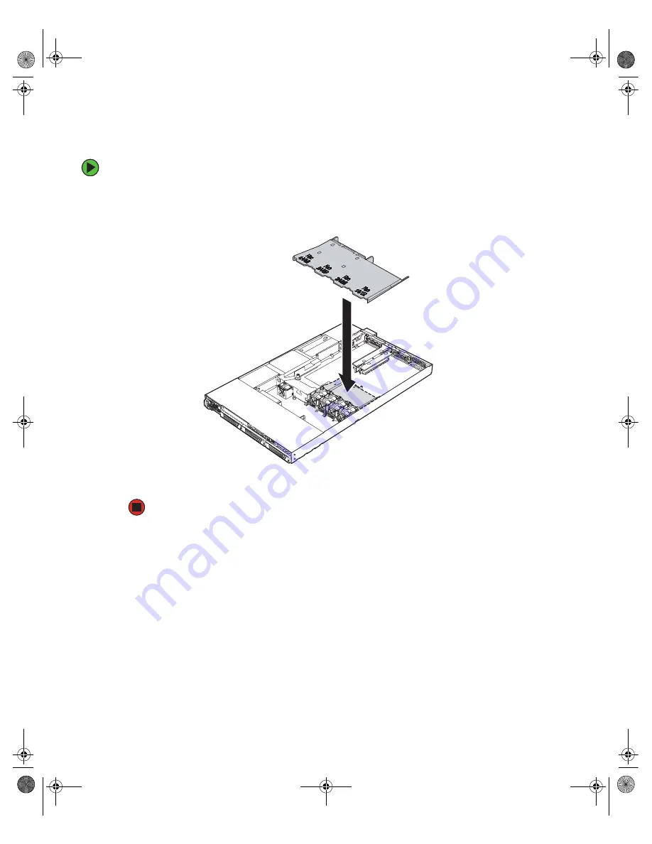
Installing the processor air duct

To install the processor air duct:

1

Place the processor air duct over the processor sockets. The front edge of the air duct 
should contact the fan module, and the top of the installed air duct should be flush 
with the top of the fan module.

2

Follow the instructions in 

“Closing the server case” on page 44

.

8510522.book  Page 48  Wednesday, March 16, 2005  11:19 AM

Summary of Contents for 9415

Page 1: ...User Guide Gateway 9415 Server ...

Page 2: ...om a cabinet 19 Starting your server 20 Understanding the power on self test 21 Turning off your server 22 Configuring the RJ 45 serial port 23 Setting up the operating system 24 Initial hardware settings 24 3 Maintaining Your Server 25 Caring for your server 26 Cleaning your server 26 Preparing for system recovery 28 Recording the BIOS configuration 28 System administration 29 Gateway Server Mana...

Page 3: ... hard drive 60 Filling empty drive bays 62 Configuring your onboard RAID solutions 62 Installing memory 66 Memory online sparing 67 Installing and removing PCI expansion cards 69 Removing and installing the PCI riser assembly 69 Removing and installing a PCI riser connector 71 Removing and installing a PCI expansion card 73 Replacing fans and fan modules 76 System fans 76 Power supply fans 80 Inst...

Page 4: ... Intel Management Modules 126 LED information 126 Diagnostic LEDs 127 BIOS 135 CD drive 135 Expansion cards 135 Hard drive 136 Internet 137 Keyboard 137 Memory 137 Monitor 137 Power 138 Processor 139 A Server Specifications 141 System specifications 142 System board specifications 143 Environmental specifications 144 Electronic specifications 145 Memory map 145 Interrupts 145 PCI interrupt routing...

Page 5: ...iv www gateway com 8510522 book Page iv Wednesday March 16 2005 11 19 AM ...

Page 6: ...Chapter 1 1 Checking Out Your Gateway Server Locating drives ports jacks and controls Locating system board components Available help resources 8510522 book Page 1 Wednesday March 16 2005 11 19 AM ...

Page 7: ...drive bay Hard drive bay Hard drive bay Hard drive activity LED LAN 1 activity indicator LAN 2 activity indicator Power button USB ports Reset button System ID button System ID LED Non maskable interrupt button recessed Power sleep LED System status LED 8510522 book Page 2 Wednesday March 16 2005 11 19 AM ...

Page 8: ...tatus LED Hard drive activity LED LAN 1 activity LED LAN 2 activity LED Power button USB port Reset button Power sleep LED System ID LED Menu scroll up USB port Menu scroll down Menu scroll left Menu scroll right LCD screen 8510522 book Page 3 Wednesday March 16 2005 11 19 AM ...

Page 9: ...eight full length PCI expansion bays Redundant power supply optional Power connectors I O panel PS 2 mouse Serialport RJ 45 LAN 1 and 2 jacks Video port USB ports External SCSI connector Diagnostic LEDs ID LED Keyboard 8510522 book Page 4 Wednesday March 16 2005 11 19 AM ...

Page 10: ...power supply optional DIMM sockets Processor air duct Power distribution board also partially under air duct Drive bay area PCI riser assembly CPU sockets Processor fan module Hot swap backplane Power supply air duct 8510522 book Page 5 Wednesday March 16 2005 11 19 AM ...

Page 11: ... Serial A header Intel Management Module IMM connector SCSI channel A IPMB SATA ports CPU socket 1 CPU socket 2 DIMM sockets 12V CPU power Power connector Control panel 50 pin ATA 100 connector Control panel diskette IDE 100 pin System fan SCSI channel B CPU 1 fan header ICMB USB header USB header System fan 8510522 book Page 6 Wednesday March 16 2005 11 19 AM ...

Page 12: ...lane Power connector Front control panel connector SCSI drive connector Mounting thumbscrew Drive LED SCSI connector from system board Drive LED Drive LED SCSI drive connector SCSI drive connector 8510522 book Page 7 Wednesday March 16 2005 11 19 AM ...

Page 13: ...on CD Gateway Web site Gateway provides a variety of information on its Web site to help you use your server Visit the Gateway Web site at support gateway com for Technical documentation and product guides Technical tips and support Updated hardware drivers Order status Frequently asked questions FAQs Telephone support You can access a wide range of services through your telephone including custom...

Page 14: ... 9 Setting Up Your Server Using your server safely Installing your server into a cabinet Starting and turning off your server Setting up your operating system 8510522 book Page 9 Wednesday March 16 2005 11 19 AM ...

Page 15: ...sed by extreme temperatures is not covered by your warranty As a general rule your server is safest at temperatures that are comfortable for you Keep your server and magnetic media away from equipment that generates magnetic fields such as unshielded stereo speakers Strong magnetic fields can erase data on both diskettes and hard drives Even a telephone placed too close to the server may cause int...

Page 16: ...ctuations in voltage from an electrical supply Most servers can handle this variation called line noise without problems However some electrical sources include more line noise than normal Line noise can also be a problem if your server is located near or shares a circuit with a device that causes electromagnetic interference such as a television or a motor Some surge protectors and uninterruptibl...

Page 17: ...s Server rails 2 Cabinet rails 2 L brackets 2 not used for this type of installation Fastener pack 1 Small screws 4 6 32 3 16 inch Medium screws 8 10 32 inch Large screws 2 10 32 7 8 inch Disk guides 2 Handle spacers 2 Nut bars 4 Caution Before attaching cabinet accessories make sure that the server is turned off and all power cords are unplugged Caution The cabinet must provide sufficient airflow...

Page 18: ... the slots with the studs and slide the rail back until it stops Your server may be different than the server shown in the example 3 Align the locking screw holes in the rails with the threaded screw holes in the server then install two locking screws through the each rail Server rail Slot Slot Threaded screw hole Locking screw hole Locking screw hole Mounting stud 8510522 book Page 13 Wednesday M...

Page 19: ...le towards the back of the server 5 Insert a small screw through the disk guide then tighten the screw Attach the remaining disk guide on the other side of the server Disk guide screw hole Disk guide screw Disk guide 8510522 book Page 14 Wednesday March 16 2005 11 19 AM ...

Page 20: ...screws but do not completely tighten the screws leave them loose enough to allow insertion of the cabinet rail in the next step 7 Insert the slotted foot at the back of each cabinet rail between the nut bar and the post then tighten the screws 8510522 book Page 15 Wednesday March 16 2005 11 19 AM ...

Page 21: ...k of the cabinet until the front of the server rails touch the front cabinet posts then secure with two screws through each server rail OR Follow the instructions in Installing the bezel on page 17 to attach both handles and secure the server into the cabinet Warning You must support the server while installing or removing the front screws and while sliding the server on or off the cabinet rails I...

Page 22: ...into the cabinet to determine which holes in the front posts of the cabinet that the holes in the handles will line up with 4 Pull the server back out of the cabinet 5 Install the mounting nuts nuts equipped with spring clips that come with most server cabinets into the holes in the front posts of the cabinet 6 Push the server into the cabinet again Important The bezel is held in place by the serv...

Page 23: ...move the bezel lock keys from the inside of the bezel then snap on the bezel with the control panel area at the right 9 To lock the bezel insert the key into the lock and rotate it turn clockwise To unlock it rotate the key turn counter clockwise 8510522 book Page 18 Wednesday March 16 2005 11 19 AM ...

Page 24: ...2 While supporting the server slide the server out from the cabinet Warning Screws are required to support the front of the server You must support the server while removing the front screws and while sliding the server off the cabinet rails If the server is not supported damage to the server or injury may result 8510522 book Page 19 Wednesday March 16 2005 11 19 AM ...

Page 25: ...at all cables are connected securely to the correct ports and jacks on the back of the server To start the server 1 Turn on any peripheral devices connected to the server 2 Press the power button Caution When you connect peripheral devices to the server make sure that your server and devices are turned off and the power cords are unplugged Power sleep LED Power button System fault LED Reset button...

Page 26: ...iguring advanced settings for your specific network Understanding the power on self test When you turn on your server the power on self test POST routine checks the server memory and components If POST finds any problems the server displays error messages Write down any error messages that you see then see Error messages on page 121 and Beep codes on page 124 for troubleshooting information When t...

Page 27: ...ssible you should use the operating system s shut down procedure instead of pressing the power button 2 If your server did not turn off automatically press the power button OR Press the reset button to reset the server Caution The power button on the server does not turn off server AC power To remove AC power from the server you must unplug the AC power cords from the wall outlet or power source T...

Page 28: ...o the server 2 Follow the instructions in Opening the server case on page 42 3 Remove the PCI riser assembly by following the instructions in Removing and installing the PCI riser assembly on page 69 4 Remove the jumper across pins 1 3 of jumper J7A1 then place the jumper across pins 2 4 5 Reinstall the PCI riser assembly by following the instructions in Removing and installing the PCI riser assem...

Page 29: ...settings to operate your server as configured However at some point you might want to change settings to reflect a tasking change a change in security requirements or the addition of new resources to your server General hardware settings as well as enabling or disabling the onboard LSI RAID solution can be changed by using the BIOS Setup utility The RAID solution can be configured by using the RAI...

Page 30: ...Chapter 3 25 Maintaining Your Server Caring for your server Recording the BIOS configuration Managing your server and network 8510522 book Page 25 Wednesday March 16 2005 11 19 AM ...

Page 31: ...sive repairs that are not covered under your warranty Avoid dusty or dirty work environments Dust and dirt can clog the internal mechanisms and can cause the server to overheat Cleaning your server Keeping your server clean and the vents free from dust helps keep your server performing at its best Your server cleaning kit could include A soft lint free cloth Glass cleaner An aerosol can of air wit...

Page 32: ...rd does not work after it dries you may need to replace it Keyboard damage resulting from spilled liquids is not covered by your warranty Cleaning the screen If your computer screen is a flat panel display use only a damp soft cloth to clean it Never spray water directly onto the screen OR If your computer screen is not a flat panel display use a soft cloth dampened with glass cleaner to clean the...

Page 33: ...em files See your operating system s documentation or online help for instructions on creating and using an emergency repair diskette Recording the BIOS configuration To help keep track of your custom changes to BIOS settings and to prepare for system recovery you should record your BIOS configuration after you have your server set up and working To record your BIOS configuration 1 Print the appen...

Page 34: ...the bezel The handles must be installed for the bezel to snap on For instructions see Installing the bezel on page 17 2 Insert the key into the lock and rotate it turn clockwise To unlock it rotate the key turn counter clockwise Using BIOS security passwords To prevent unauthorized use of the server you can set server startup passwords Set an administrator password to prevent unauthorized access t...

Page 35: ...ller and is independent of the operating system Its 4 20 display provides information directly from the Baseboard Management Controller BMC using the IPMB bus Interactions The LCP can Poll the BMC to determine alert conditions Query the BMC for system event log entries Display and control the power state of the server Query the BMC for field replaceable units FRUs Read BMC sensors Retrieve BIOS PO...

Page 36: ...tion Configure the server Network LAN channel 1 to 3 IP address BMC Netmask Gateway address Enable LAN channel Configure TCO NIC Inventory CPUs DIMMs Drives Power supplies System fans View system inventory Server name View server name Asset tab information View asset tag Server GUID View server GUID Scroll up Scroll down Scroll left or to previous option Scroll right or to previous page 8510522 bo...

Page 37: ...ogress codes Server health drill down to subsystem s at fault View the health of the system System event log View the system event log CPU sensors CPU 1 to n Presence Over temperature On off line View CPU related status Chassis status Intrusion status Power supply 1 to n Presence Status Fan 1 to n Presence Status Speed HSC 1 to 2 Presence Status View chassis related status Temperatures all availab...

Page 38: ...ctionality as if done over LAN or by GSM IPMI command screen Issue an IPMI command text or hex Issue an IPMI command Set up the server Language selection display loaded language files Select the LCP display language Status setup Interval timing set time to retrieve status Subsystem mask mask off subsystems Set sensor refresh interval Password setup Password exists does not exist Create change pass...

Page 39: ...ed to be turned on but it does need to be plugged in To turn on the System ID indicator 1 Press the System ID button The two blue System ID LED indicators turn on 2 To turn off the indicator press the System ID button Important If your server has an Intel IMM module installed the system ID LED will turn on or off when the System ID button is pressed If no IMM Module is installed the system ID LED ...

Page 40: ...quent firmware updates do not To update the BMC firmware without boot block update 1 Create a DOS bootable USB Disk on key device or a DOS bootable CD 2 Download the BMC update file from support gateway com 3 Follow the instructions included with the update file 4 Turn off the server then disconnect the power cord s and wait for the Standby power LED to turn off To update the BMC firmware with boo...

Page 41: ...able USB Disk on key device or DOS bootable CD 8 Download the BMC update file from support gateway com 9 Follow the instructions included with the update file 10 Turn off the server then disconnect the power cord s and wait for the Standby power LED to turn off 11 Follow the instructions in Opening the server case on page 42 Important Jumper J1B1 is located on the IMM Module board Jumper J1B1 on t...

Page 42: ...he FRU SDR 1 Boot your server to DOS using a DOS bootable diskette CD or USB disk on key 2 Put the System Companion CD in the CD drive and change directories to the CD drive to access it 3 When the System Companion CD menu opens select the FRU SDR utility 4 Select one of the following options if in doubt choose the second option and update both Update just the SDR repository Select this option whe...

Page 43: ...ion CD You can use your System Companion CD to Install hardware drivers Install programs View server documentation Instructions for using the CD are provided in Using Your System Companion CD 8510522 book Page 38 Wednesday March 16 2005 11 19 AM ...

Page 44: ...nstalling and replacing major components You must open your server case to install components If you are not comfortable with these procedures get help from a computer service technician or contact Gateway Customer Care 8510522 book Page 39 Wednesday March 16 2005 11 19 AM ...

Page 45: ...ne jack and cannot be connected to your server Gathering the tools you need Some tools and supplies that you may need to work on your server are A notebook to take notes A Phillips screwdriver A small flat blade screwdriver Small containers to store various types of screws A grounding wrist strap available at most electronic stores Getting Help If you have questions about performing any of these p...

Page 46: ...humid Remove components from their antistatic bags only when you are ready to use them Do not lay components on the outside of antistatic bags because only the inside of the bags provide electrostatic protection Always hold expansion cards by their edges or their metal mounting brackets Avoid touching the edge connectors and components on the cards Never slide expansion cards or components over an...

Page 47: ... For instructions see Removing the server from a cabinet on page 19 4 Place the server on a stable non skid surface 5 Remove the shipping screw if installed Caution For correct cooling and air flow always reinstall the top panel before you turn on the server Operating the server without the panel in place will cause the server to overheat Warning This server has two power cords To disconnect inter...

Page 48: ...Press and hold the panel release button then slide the top panel toward the back of the server about inch 7 Lift the top panel away from the server Panel release button 8510522 book Page 43 Wednesday March 16 2005 11 19 AM ...

Page 49: ...side the case so they will not be pinched when you close the case 2 Slide the top panel onto the server 3 Slide the top panel toward the front of the server until it clicks into place 4 Replace the shipping screw if necessary 5 Reconnect the power cords and all other cables 8510522 book Page 44 Wednesday March 16 2005 11 19 AM ...

Page 50: ... s The air duct will need to be removed if you need to add or remove a processor in your system or if you need to replace the system board To remove the processor air duct 1 Follow the instructions in Preventing static electricity discharge on page 41 Make sure that you turn off the server then unplug the power cord s and all other cables connected to the server 2 Follow the instructions in Openin...

Page 51: ...static electricity discharge on page 41 Make sure that you turn off the server then unplug the power cord s and all other cables connected to the server 2 Follow the instructions in Opening the server case on page 42 3 Follow the instructions in Removing the processor air duct on page 45 Caution If you add a second processor to your server you must remove the processor air dam or the processor may...

Page 52: ... Installing the processor air duct on page 48 6 Follow the instructions in Closing the server case on page 44 Important This procedure requires that the air dam be broken off the air duct After this is done the air duct is no longer suitable for use with only a single processor installed 8510522 book Page 47 Wednesday March 16 2005 11 19 AM ...

Page 53: ...essor air duct over the processor sockets The front edge of the air duct should contact the fan module and the top of the installed air duct should be flush with the top of the fan module 2 Follow the instructions in Closing the server case on page 44 8510522 book Page 48 Wednesday March 16 2005 11 19 AM ...

Page 54: ...ver then unplug the power cord s and all other cables connected to the server 2 Follow the instructions in Opening the server case on page 42 3 Move cables out of the way 4 Unscrew the phillips screw holding the power supply air duct in place 5 Pull up on the air duct to remove it from the server chassis Caution To ensure continued reliable operation always operate your server with the appropriate...

Page 55: ...ce 3 Rearrange cables as they were prior to removal of the air duct 4 Follow the instructions in Closing the server case on page 44 Caution To ensure continued reliable operation always operate your server with the appropriate air ducts and air dams in place Failure to do this could result in equipment damage Caution Make sure you do not pinch any cables under the air duct as you are reinstalling ...

Page 56: ...ou need to install a diskette drive and a CD or DVD drive is installed in the slim line drive bay you must install the diskette drive in a converted hard drive bay Before you install a drive see the drive s documentation for information on configuring the drive setting drive jumpers and attaching cables You may need to configure the drives you install using the BIOS Setup utility Press F2 at start...

Page 57: ...r cord s and all other cables connected to the server 2 Follow the instructions in Opening the server case on page 42 3 Unlock the bezel if necessary and remove it by pulling it from the chassis 4 Remove the center hot swap hard drive carrier from the server 5 xxxRemove the rails from the diskette drive conversion kit carrier by removing the four screws that secure the rails to the carrier Caution...

Page 58: ...elight down facing down 7 Align the holes in the sides of the diskette drive with the holes in the carrier and attach the drive to the carrier with the two screws that came with the diskette drive conversion kit 8 Reattach the rails to the sides of the carrier with the four screws you previously removed 8510522 book Page 53 Wednesday March 16 2005 11 19 AM ...

Page 59: ...Install the other end of the flat flex cable to the interposer board included in the diskette drive conversion kit 12 Install the interposer board on the diskette drive carrier with one screw on the right side 13 Connect the data and power cables to the interposer board 14 While guiding the cables insert the new drive assembly into the center hard drive bay until it clicks into place Interposer bo...

Page 60: ...ve it by pulling it from the chassis 4 Disconnect the data cable from the system board See System board on page 6 for the location of the connectors on the system board 5 Disconnect the power cable from the back of the interposer board 6 Push in on the blue lever at the back of the drive carrier to release the drive carrier from the drive bay then slide the diskette drive carrier and cables out th...

Page 61: ...VD drive 1 Follow the instructions in Preventing static electricity discharge on page 41 Make sure that you turn off the server then unplug the power cord s and all other cables connected to the server 2 Unlock the bezel if necessary and remove it by pulling it from the chassis 3 Follow the instructions in Opening the server case on page 42 4 Disconnect the 44 pin CD drive cable from the system bo...

Page 62: ...er 7 Press down on the side of the drive carrier to release the drive from the carrier 8 Disconnect the 44 pin CD drive cable from the back of the interposer board 9 Pull up on the top of the connector on the back of the CD or DVD drive and remove the flat flex cable 10 Remove the four screws securing the rails to the carrier then remove the rails Interposer board CD or DVD drive Screws Drive carr...

Page 63: ...CD or DVD drive To install a CD or DVD drive 1 Follow the instructions in Preventing static electricity discharge on page 41 Make sure that you turn off the server then unplug the power cord s and all other cables connected to the server 2 Follow the instructions in Opening the server case on page 42 3 Unlock the bezel if necessary and remove it by pulling it from the chassis 4 Remove the CD DVD d...

Page 64: ...r on the back of the CD or DVD drive then attach the board to the drive with two screws included with your server 7 Attach the 44 pin CD drive cable to the back of the interposer board 8 Slide the CD or DVD drive assembly into the slim line bay until it clicks into place 9 Connect the other end of the 44 pin cable into the connector on the system board See System board on page 6 for the location o...

Page 65: ...k the bezel if necessary and remove it by pulling it from the chassis 2 Press the green release button on the hot swap tray lever then swing the lever open all the way 3 Pull the drive carrier straight out of the server Important Gateway tests and verifies the operation and compatibility of the drives it sells Especially in a hot swap or mission critical environment additional or replacement drive...

Page 66: ...the screw holes in the new drive with the holes in the side of the drive tray then secure the drive to the tray with the four screws you removed in Step 4 6 Make sure that the tray s release lever is open then slide the new drive into the empty hot swap bay 7 When the drive carrier lever begins to close by itself push on the lever to lock the drive assembly into the drive bay 8 Reinstall the bezel...

Page 67: ... BIOS console 1 Restart your server 2 Press F2 when the Gateway logo screen appears during startup The BIOS Setup utility opens 3 From the Main BIOS menu select the Advanced menu 4 Select the PCI Configuration sub menu 5 For the Onboard SCSI option click Enabled 6 Exit the BIOS Setup utility 7 Restart your server Level Description and use Pros Cons Number of drives Fault Tolerant 0 Data divided in...

Page 68: ...e excess space of larger member disks is not used To configure the onboard SCSI RAID solution for Integrated Mirroring 1 Open the BIOS Setup utility as described in the previous procedure 2 On the Main menu screen use the arrow keys to select an adapter then press ENTER The Adapter Properties screen opens 3 Use the arrow keys to select RAID Properties then press ENTER The RAID Properties screen op...

Page 69: ...ntroller An IS volume can have two or three disks Disks in an IS volume must be non removable single LUN disks that support 512 byte sectors wide synchronous transfers Qtag d I Os and a unit serial number The disks must support SMART and they must be minimally compliant with the SCSI 2 standard Disks of different size are allowed in IS volumes but the smallest disk determines the logical size of e...

Page 70: ...step to select as many as two more disks for the striped volume If partitions are defined on the selected disks a message appears warning you that data on the disk will be lost when the striped volume is created You can then deselect that disk or erase the disk and continue 6 When you have selected all disks for the IS volume press ESC and select Save changes then exit this menu If you do not want...

Page 71: ...ing the following guidelines DIMM banks must be populated in order starting with Bank 1 Dual rank double row DIMMs must be populated before single rank DIMMs Caution Modules must be installed in banks in identical pairs Use only DDR2 400 compliant 240 pin SDRAM registered ECC DIMM memory modules Memory modules must be installed in pairs to completely fill each bank and the banks must be filled in ...

Page 72: ...pare DIMM must be equal to or larger than the largest DIMM in that channel If a DIMM begins to fail the contents of the failing DIMM is copied to the spare DIMM in that channel When all of the data is copied the primary DIMM is automatically removed from service Since one DIMM per channel is always Supported DDR2 400 DIMM populations Bank 1 DIMMs 1A and 1B Bank 2 DIMMs 2A and 2B Bank 3 DIMMs 3A an...

Page 73: ...ons in Opening the server case on page 42 3 Pull the plastic tabs away from the sides of the memory module slot If you are replacing a memory module lift the old module out of the slot 4 Align the notch on the new module with the notch in the memory module slot and press the module firmly into the slot The tabs on the sides of the memory slot should secure the memory module automatically 5 Follow ...

Page 74: ...u are replacing a card disconnect any cables that are attached to the old card Caution Always operate your server with the PCI riser assembly in place The PCI riser assembly is important for correct airflow within the server Operating the server without the PCI riser assembly in place could result in overheating and possible data loss or equipment damage Caution The PCI riser assembly and individu...

Page 75: ...ion card follow the instructions in Removing and installing a PCI expansion card on page 73 OR If you are installing or replacing the PCI riser connector follow the instructions in Removing and installing a PCI riser connector on page 71 Caution Do not touch the contacts on the bottom part of the expansion card Touching the contacts can cause electrostatic damage to the card 8510522 book Page 70 W...

Page 76: ... s documentation for software installation instructions Removing and installing a PCI riser connector Included with your server were two full height PCI riser connectors only one of which can be used at a time A full height PCI Express riser with one PCI Express x8 slot A full height PCI X riser with one PCI X slot A full height PCI riser connector can be replaced if it fails or if you require a d...

Page 77: ...g a PCI expansion card on page 73 5 Push back on the blue riser locking lever at the end of the PCI riser connector 6 While holding the lever in push firmly on the other edge of the PCI riser connector to disengage the connector from the riser retention pins 7 Place the PCI riser connector in a static free bag to store it for future use Important To eliminate the possibility of installing the repl...

Page 78: ...tructions in Removing and installing the PCI riser assembly on page 69 13 Follow the instructions in Closing the server case on page 44 14 See the card s documentation for software installation instructions Removing and installing a PCI expansion card To remove and install a PCI expansion card 1 Follow the instructions in Preventing static electricity discharge on page 41 Make sure that you turn o...

Page 79: ...or storage You can gently rock the card end to end to loosen and remove the card do not bend the card sideways then proceed to Step 7 OR If you need to change out the PCI riser connector follow the instructions in Removing and installing a PCI riser connector on page 71 Caution Do not touch the contacts on the bottom part of the expansion card Touching the contacts can cause electrostatic damage t...

Page 80: ...required cables to the card by following the instructions in the card s documentation 10 Install the PCI riser assembly by following the instructions in Removing and installing the PCI riser assembly on page 69 11 Follow the instructions in Closing the server case on page 44 12 See the card s documentation for software installation procedures Important If you are installing a low profile PCI expan...

Page 81: ...e monitored by the Gateway Server Manager GSM the mini Baseboard Management Controller BMC and the Intel Management Module IMM All three reporting entities use a different numbering system to flag individual fans for attention Individual system fan module fan numbers are indicated on the top of the processor air duct The first number in the pair is for the fan closest to the front of the server Ca...

Page 82: ...g the processor air duct on page 45 4 Trace the cable from the failed fan to the connector on the fan distribution board then disconnect the cable 5 Lift the fan from the fan module in the chassis 6 Insert the replacement fan into the fan module 7 Connect the fan cable to the connector on the fan distribution board Important Make sure that the arrows on top of the fans indicating airflow point to ...

Page 83: ... cables connected to the server 2 Follow the instructions in Opening the server case on page 42 3 Disconnect the fan cable from the connector on the power distribution board 4 Lift the failed fan from the fan bracket 5 Insert the replacement fan into the fan bracket Caution System fans are not hot swappable Before removing or replacing a fan you must first turn off the server and all peripheral de...

Page 84: ...ndicating airflow points to the back of the chassis The fan cable should exit the fan mudule toward the back of the chassis Caution System fans are not hot swappable Before removing or replacing a fan you must first turn off the server and all peripheral devices attached to the server and remove the AC power cord s from the power supply or wall outlet 8510522 book Page 79 Wednesday March 16 2005 1...

Page 85: ...s reported the server must be opened to determine which fan is having problems LEDs on the power distribution board will indicate which fan requires attention The appropriate LED will blink to indicate a slow fan and light to show a failed fan The PS Fan 1 is on the left side of the module To replace a power supply fan 1 Follow the instructions in Preventing static electricity discharge on page 41...

Page 86: ... the power supply fan module assembly 7 Connect the fan cable to the connector on the power distribution board 8 Follow the instructions in Installing the power supply air duct on page 50 9 Follow the instructions in Closing the server case on page 44 Important Make sure the arrows on top of the fans indicating airflow point to the back of the chassis The fan cable should exit the fan mudule towar...

Page 87: ... Follow the instructions in Opening the server case on page 42 4 Follow the instructions in Removing the processor air duct on page 45 Warning Processors and heat sinks may be hot if the computer has been running Before replacing a processor or heat sink allow them to cool for several minutes Caution A heat sink must be installed on the processor Installing a processor without a heat sink could da...

Page 88: ... release lever a full 135 to release the processor then lift the processor out of the socket Caution The heat sink has Thermal Interface Material TIM on the bottom Be careful not to damage this material when you remove the heat sink from the processor If removing the heat sink also pulls the processor out of the processor socket the processor could be damaged 8510522 book Page 83 Wednesday March 1...

Page 89: ...rom the closed position The triangular arrow on the corner of the processor aligns with the triangular icon on the corner of the processor socket 10 Install the new processor into the processor socket then press the processor locking lever down until it lays flat against the processor socket Caution If you add a second processor to your server you must remove the processor air dam or the processor...

Page 90: ...Do not fully tighten one screw before tightening another 13 Gradually and equally tighten each captive screw until each is firmly tightened Do not over tighten the screws 14 Follow the instructions in Installing the processor air duct on page 48 15 Follow the instructions in Closing the server case on page 44 Caution The heat sink has Thermal Interface Material TIM located on the bottom of it Use ...

Page 91: ...tic electricity discharge on page 41 Make sure that you turn off the server then unplug the power cord s and all other cables connected to the server 3 Follow the instructions in Opening the server case on page 42 4 Remove the riser assembly by following the instructions in Removing and installing the PCI riser assembly on page 69 5 Install the nylon standoff into the corner hole in the IMM module...

Page 92: ...llowing the instructions in Removing and installing the PCI riser assembly on page 69 9 Follow the instructions in Closing the server case on page 44 10 Following the installation of a new IMM module reinstall the GSM software supplied on a CD with your server and update the FRU SDR see Updating the FRU SDR on page 37 When you subsequently reboot your server the GSM software will take over managem...

Page 93: ...th more than one power supply module determine which power supply module has failed the LED on the power supply will be orange 2 If your server has only one power supply module installed disconnect the AC power cord before continuing OR If your server has two power supply modules installed you do not need to turn off the power to the server before continuing Caution The power supplies in this serv...

Page 94: ... out of the server with the handle 5 Insert the new power supply module into the server with the green locking lever to the left until it locks into place then fold the handle flat 6 Reconnect the AC power cord for the new power supply module 7 If you added a redundant power supply module see Updating the FRU SDR on page 37 Locking lever Handle Power supply LED 8510522 book Page 89 Wednesday March...

Page 95: ...ng the power supply air duct on page 49 4 Remove the power supply modules by following the instructions in Replacing a power supply module on page 88 5 Disconnect the main power CPU power and power signal cables from the system board See System board on page 6 for the location of the connectors on the system board 6 Disconnect the PCI fan from the power distribution board 7 Disconnect the power ca...

Page 96: ...om the power distribution board to the system board See System board on page 6 for the location of the connectors on the system board 12 Reconnect the PCI fan to the power distribution board 13 Reconnect the power cables to the power distribution board and the hot swap backplane 14 Reconnect the drive cables and drive power cables to the hot swap backplane 15 Reinstall the power supply modules by ...

Page 97: ...all the power supply air duct by following the instructions in Installing the power supply air duct on page 50 17 Follow the instructions in Closing the server case on page 44 8510522 book Page 92 Wednesday March 16 2005 11 19 AM ...

Page 98: ...ng the server case on page 42 4 Remove all of the hot swap drive carriers from the server and make note of which bay you remove each drive from For instructions see Installing a hard drive on page 60 5 Disconnect all cables from the backplane 6 Loosen the blue captive thumbscrew in the middle of the backplane Caution The hot swap backplane is not hot swappable Before removing or replacing the back...

Page 99: ...Follow the instructions in Closing the server case on page 44 14 Reinstall the hot swap drives back into the server Make sure that you install the drives into the same bays you removed them from in Step 4 For instructions see Installing a hard drive on page 60 15 Replace the bezel by snapping it into place on the front of the server Caution Pressing or pulling on any components on the backplane co...

Page 100: ...tout then close the utility 4 Turn off your server then follow the instructions in Preventing static electricity discharge on page 41 5 Follow the instructions in Opening the server case on page 42 6 Remove the PCI riser assembly by following the instructions in Removing and installing the PCI riser assembly on page 69 Warning Danger of explosion if battery is incorrectly replaced Replace only wit...

Page 101: ...ng up then press the new battery into the socket until it snaps into place 10 Replace the PCI riser assembly by following the instructions in Removing and installing the PCI riser assembly on page 69 11 Follow the instructions in Closing the server case on page 44 12 Turn on your server then press F2 when the Gateway logo screen appears during startup The BIOS Setup utility opens 13 Restore any BI...

Page 102: ...les connected to the server 2 Follow the instructions in Opening the server case on page 42 3 Unlock the bezel if necessary and remove it by pulling it straight out from the front of the chassis 4 Disconnect the front panel cable from the backplane Caution Your server must be operated with a control panel module in place Important Correct operation of the optional LCP control panel module requires...

Page 103: ...the back of the control panel module then slide the module out of the chassis enough to reach the USB cable Blue latch Standard control panel module Blue latch Optional LCP control panel module 8510522 book Page 98 Wednesday March 16 2005 11 19 AM ...

Page 104: ...you connect the USB cable Caution The USB header has a latch to hold the connector on Be careful to unlatch the USB connector when removing it from the control panel or you could damage the connector or the header Important The position of the USB connector is different in the standard control panel than in the optional local control panel Note the positions of the cable connectors as you remove t...

Page 105: ...trol panel module tray 1 With the LCP control panel module tray removed from the server locate the blue thumbscrew that secures the tray extension in position on the module tray Important If you are replacing the standard control panel module with the optional LCP control panel module and decide to use the optional bezel you are required to reconfigure the LCP module for use with the bezel For inf...

Page 106: ... be replaced with the new sub bezel included with your server To replace the sub bezel 1 Use a flat blade screwdriver to lift the metal retention tabs on both sides of the LCP control panel module then pull the sub bezel off of the front of the module 2 Align the new sub bezel with the LCP control panel then press it until it clicks into place Warning Use a flat blade screwdriver to lift the metal...

Page 107: ...on page 45 4 Remove the PCI riser assembly by following the instructions in Removing and installing the PCI riser assembly on page 69 5 Remove the memory modules by following the instructions in Installing memory on page 66 6 Remove the fan module by following the instructions in Replacing fans and fan modules on page 76 7 Remove the heat sinks and processors by following the instructions in Insta...

Page 108: ...103 www gateway com 9 Remove the 7 screws that secure the system board to the server Screw Screw Screw Screw Screw Screw Screw 8510522 book Page 103 Wednesday March 16 2005 11 19 AM ...

Page 109: ...de the system board toward the front of the server If the board is difficult to move push on the back I O port panel for added leverage 11 Lift the board away from the case 8510522 book Page 104 Wednesday March 16 2005 11 19 AM ...

Page 110: ...low the instructions in Installing a processor on page 82 16 Follow the instructions in Replacing fans and fan modules on page 76 17 Reinstall the PCI riser assembly by following the instructions in Removing and installing the PCI riser assembly on page 69 18 Follow the instructions in Closing the server case on page 44 19 Turn on your server then press F2 when the Gateway logo screen appears duri...

Page 111: ...r s new hardware then save your changes if any and close the BIOS Setup utility 21 If your server does not start after installing the new system board contact Gateway Customer Care For more information see Getting Help on page 8 8510522 book Page 106 Wednesday March 16 2005 11 19 AM ...

Page 112: ...Using the BIOS Setup Utility Opening the BIOS Setup utility Updating the BIOS Resetting the BIOS settings to their factory defaults Resetting the BIOS passwords 8510522 book Page 107 Wednesday March 16 2005 11 19 AM ...

Page 113: ...ated to your server s hardware and configuration Advanced gives you access to information and settings for PCI peripheral devices memory and the chipset Security gives you access to settings related to system access passwords For more information see Server security on page 29 Server gives you access to settings for system management console redirection event log configuration and fault resilient ...

Page 114: ... into two partitions a primary active partition from which the server boots and a secondary partition to which BIOS updates are diverted When a BIOS update occurs the existing BIOS image is preserved on the primary partition and the system is automatically prompted to attempt to boot from the new BIOS on the secondary partition If a boot failure occurs with the new BIOS the system will revert to t...

Page 115: ...n disconnect the power cords and all other cables connected to the server 7 Follow the instructions in Opening the server case on page 42 8 Place the jumper back onto pins 1 2 9 Follow the instructions in Closing the server case on page 44 Recovering the BIOS If you encounter a problem while you are updating the BIOS such as a power outage the BIOS update may not be successful If the system contin...

Page 116: ...o the server 2 Follow the instructions in Opening the server case on page 42 3 Remove the jumper across pins B1 B2 then place the jumper across pins B2 B3 4 Follow the instructions in Closing the server case on page 44 Caution Moving the jumper while the power is on can damage your server Always turn off the server and unplug the power cords and all other cables before changing the jumper 8510522 ...

Page 117: ... is complete when the server stops beeping 7 Remove the bootable USB disk on key 8 Turn off the server then disconnect the power cords and all other cables connected to the server 9 Follow the instructions in Opening the server case on page 42 10 Place the jumper back onto pins B1 B2 11 Follow the instructions in Closing the server case on page 44 12 Plug in the AC power cords and turn on the serv...

Page 118: ...y custom BIOS settings on your printout 4 Press the reset button and hold it down for four seconds or more then press the power button while continuing to hold down the reset button 5 Release both buttons at the same time The BIOS is reset To reset the BIOS using the system board jumper 1 Turn off the server then disconnect the power cords and all other cables connected to the server 2 Follow the ...

Page 119: ...r cords and all other cables connected to the server 7 Follow the instructions in Opening the server case on page 42 8 Place the jumper back onto pins C1 C2 9 Follow the instructions in Closing the server case on page 44 Resetting BIOS passwords To reset BIOS passwords you must either reset and clear all BIOS settings or use the Clear Password jumper To reset all BIOS settings follow the instructi...

Page 120: ...t the power cords and turn on the server The BIOS password s is cleared 6 Turn off the server then disconnect the power cords and all other cables connected to the server 7 Follow the instructions in Opening the server case on page 42 8 Place the jumper back onto pins A1 A2 9 Follow the instructions in Closing the server case on page 44 Caution Moving the jumper while the power is on can damage yo...

Page 121: ...116 www gateway com 8510522 book Page 116 Wednesday March 16 2005 11 19 AM ...

Page 122: ...nd training Interpreting error messages and codes Troubleshooting If the suggestions in this chapter do not correct the problem see Telephone support on page 118 for more information about how to get help 8510522 book Page 117 Wednesday March 16 2005 11 19 AM ...

Page 123: ...pport resources If you have how to questions about using a program see The program s online Help The program s documentation Your operating system s documentation The software or hardware manufacturer s Web site See Troubleshooting on page 123 Have your client ID serial number usually located on the back of your server case and order number available along with a detailed description of your issue...

Page 124: ...for software issues 800 229 1103 charged to your credit card Gateway Customer Care Talk to a Gateway Customer Care representative about a non tutorial technical support question 877 485 1464 US option 6 800 846 3609 Canada and Puerto Rico 605 232 2191 all other countries Sales accounting and warranty Get information about available systems pricing orders billing statements warranty service or othe...

Page 125: ... damage from static electricity see Preventing static electricity discharge on page 41 After you complete any maintenance task where you have to open the server case make sure that you close the case and reconnect all cables before you restart your server Warning To avoid bodily injury do not attempt to troubleshoot your server problem if The power cords or plugs are damaged Liquid has been spille...

Page 126: ...Make sure that the correct drive type is selected Hard disk controller failure press F1 to try reboot The drive controller may be defective Press F1 to try to restart the server For more information about running diagnostics on your hard drive see your operating system s documentation Insert bootable media device Restart your server then open the BIOS Setup utility by pressing and holding F2 while...

Page 127: ...ory errors were detected during server start up on page 137 for a possible solution Memory size error Restart your server then open the BIOS Setup utility by pressing and holding F2 while your server restarts Save the memory configuration Missing operating system The master boot record may be corrupt For troubleshooting information see The master boot record is corrupted on page 137 System Event L...

Page 128: ... write down the exact message before calling Gateway Customer Care For instructions see Telephone support on page 118 Restart your server then open the BIOS Setup utility by pressing and holding F2 while your server restarts Check your configuration settings When diagnosing problems press the non maskable interrupt NMI button with a straightened paper clip to put the server into a halt state For t...

Page 129: ... tones during POST if the video configuration fails a faulty video controller or if an expansion card is not functioning correctly One short beep indicates the BIOS will boot the operating system No error found A PCI expansion card for example a RAID controller can also issue audible errors by itself usually consisting of one long tone followed by a series of short tones For more information on th...

Page 130: ...talled then try a known good processor in the first socket Same as for 4 beeps 6 The keyboard controller 8042 may be defective The BIOS cannot switch to Protected mode Remove the keyboard to see if the error goes away If it does try a known good keyboard Same as for 4 beeps 7 General exception error processor exception error Same as for 5 beeps 8 Display memory error system video adapter If the sy...

Page 131: ...led processor 1 5 2 3 Processor configuration error or CPU 1 socket is empty Reseat or replace the failed processor In a two processor system make sure the processors are identical 1 5 2 4 Front side bus select configuration error 1 5 4 2 DC power unexpectedly lost 1 5 4 3 Chipset control failure 1 5 4 4 Power control failure LED Name Function Location Color Description ID Aid in server identifica...

Page 132: ...80 POST code On the left back of the system board Each LED can be Off Green Orange or Red See the following Post Code Table CPU 1 and 2 Fan Fault Identify fan failure At the front center of the system board Orange On Fault CPU 1 and 2 Fault Identify processor failure On the system board 1 behind the processor socket Orange On Fault 5v Standby Identify 5v standby power on state At the front left of...

Page 133: ...ompatible PICs in the system 05 Off G Off G Initialize the interrupt controller in hardware generally PIC and interrupt vector table 06 Off G G Off Do R W test to CH 2 count reg Initialize CH 0 as system timer Install the POSTINT1Ch handler Enable IRQ 0 in PIC for system timer interrupt Trap INT1Ch vector to POSTINT1ChHandlerBlock 08 G Off Off Off Initialize the CPU The BAT test is being done on K...

Page 134: ...nguage and font modules for ADM Activate ADM module 33 Off Off O O Initialize the silent boot module Set the window for displaying text information 37 Off G O O Displaying sign on message CPU information setup key message and any OEM specific information 38 G Off R R Initialize different devices through DIM See DIM code checkpoints on page 134 for more information 39 G Off R O Initialize DMAC 1 an...

Page 135: ...ble NMI as selected 90 R Off Off R Late POST initialization of system management interrupt A0 R Off R Off Check boot password if installed A1 R Off R G Clean up work needed before booting to operating system A2 R Off O Off Take care of runtime image preparation for different BIOS modules Fill the free area in F000h segment with 0FFh Initializes the Microsoft IRQ Routing Table Prepares the runtime ...

Page 136: ...Early chipset initialization is done Early super I O initialization is done including RTC and keyboard controller NMI is disabled D1 R R Off O Perform keyboard controller BAT test Check if waking up from power management suspend state Save power on CPUID value in scratch CMOS D0 R R Off R Go to flat mode with 4 GB limit and GA20 enabled Verify the bootblock checksum D2 R R G R Disable CACHE before...

Page 137: ... in memory D9 O R Off O Store the Uncompressed pointer for future use in PMM Copying Main BIOS into memory Leaves all RAM below 1 MB Read Write including E000 and F000 shadow areas but closing SMRAM DA O R G R Restore CPUID value back into register Give control to BIOS POST ExecutePOSTKernel See POST code checkpoints on page 128 for more information E1 E8 EC EE OEM memory detection configuration e...

Page 138: ...he current configuration of the flash part FB O R O O Make flash write enabled through chipset and OEM specific method Detect correct flash part Verify that the found flash part size equals the recovery file size F4 R O R R The recovery file size does not equal the found flash part size FC O O R R Erase the flash part FD O O R O Program the flash part FF O O O O The flash has been updated successf...

Page 139: ...rd peripherals memory and I O decode windows in PCI PCI bridges and noncompliant PCI devices Static resources are also reserved Boot Output Device Initialization function 2 Searches for and initializes any PnP PCI or AGP video devices 38 Initialize different buses and perform the following functions Boot Input Device INitialization function 3 Searches for and configures PCI input devices and detec...

Page 140: ... off your server then remove the drive and push it in again to make sure the drive is seated correctly For instructions see Installing a CD or DVD drive on page 58 Your CD drive tray does not open Press a straightened paper clip wire into the CD drive s manual eject hole The drive tray opens If this problem happens frequently while the server is turned on the drive may be defective Expansion cards...

Page 141: ...e SCSI controller is enabled in the BIOS Setup utility Reinstall the device driver For instructions see Using Your System Companion CD Change the drive s SCSI address to one that is not being used by your server For more information about SCSI device configurations see your drive s documentation Run SCSI Verify in the SCSI BIOS For more information about the SCSI BIOS see the SCSI controller s doc...

Page 142: ...you spilled liquid in the keyboard turn off your server and unplug the keyboard Clean the keyboard and turn it upside down to drain it Let the keyboard dry before using it again If the keyboard does not work after it dries you may need to replace it This type of damage is not covered by your server s warranty Memory Memory errors were detected during server start up Open your server and make sure ...

Page 143: ... light to pass through the screen for brighter colors and greater luminescence The damper wire is a critical part of the overall monitor design and does not negatively affect the monitor s function Power You press the power button but the server does not turn on If the power button LED is green the server is turned on but you may not be seeing an image on the monitor For monitor troubleshooting se...

Page 144: ...automatically if it is installed correctly Set the Retest Processor option in the BIOS Setup utility to Yes If you have upgraded your server from one processor to two you may need to reconfigure your operating system so it recognizes the additional processor For instructions see your operating system s documentation 8510522 book Page 139 Wednesday March 16 2005 11 19 AM ...

Page 145: ...140 www gateway com 8510522 book Page 140 Wednesday March 16 2005 11 19 AM ...

Page 146: ...er Specifications The following specifications are for the standard configuration Your server may contain optional equipment All specifications are subject to change 8510522 book Page 141 Wednesday March 16 2005 11 19 AM ...

Page 147: ...ional with optional LCP front panel Serial RJ 45 VGA 2 standard only 1 with optional LCP front panel U320 high density SCSI 1 LAN 2 RJ 45 Drives standard One slimline drive bay for a CD drive standard or a DVD drive optional Card sizes Supports one full length full height and one low profile PCI expansion card Power supply One 520 W hot swap power supply module standard Additional 520 W hot swap r...

Page 148: ...is supported This means a maximum of four dual rank DIMMs can be populated on this system board PCI device slot PCI riser assembly featuring One full length full height 64 bit PCI riser PCI PCI X or PCI Express which supports one card One low profile LP 64 bit PCI X riser up to 66 MHz which supports one card VGA On board ATI Rage XL 8 MB SDRAM Up to 1600 1200 2D and 3D LAN Intel 82546GB controller...

Page 149: ... idle state at typical office ambient temperature 73 4 F Sound Power 7 0 BA in an idle state at typical office ambient temperature 73 4 3 6 F Shock Operating 2 0 g 11 mSec 1 2 sine Unpackaged Trapezoidal 25 g velocity change 136 inches sec 40 lbs to 80 lbs Packaged Non palletized free fall in height 24 inches 40 lbs to 80 lbs Vibration 5 Hz to 500 Hz 2 20 g RMS random Electrostatic discharge ESD T...

Page 150: ...8 KB Video or SMM memory 0C0000h and 0DFFFFh 128 KB Expansion card BIOS and buffer area 0E0000h to 0FFFFFh 128 KB System BIOS 0E0000h to 0EFFFFh 2 MB Extended system BIOS FC000000h to FFFFFFFFh 64 MB PCI memory space Important If you disable an IDE controller to free the interrupt for that controller you must physically unplug the IDE cable from the system board Simply disabling the drive by confi...

Page 151: ...condary ATA legacy mode PIRQA USB 2 0 controller 1 and 4 PIRQB Video PIRQC USB 2 0 controller 3 Native IDE SATA PIRQD USB 2 0 controller 2 PIRQE Option for SCI TCO HPET 0 1 2 PIRQF Option for SCI TCO HPET 0 1 2 PIRQG Option for SCI TCO HPET 0 1 2 PIRQH USB 2 0 EHCI controller 1 Option for SCI TCO HPET 0 1 2 Ser IRQ SIO3 Device Interrupt A Interrupt B Interrupt C Interrupt D Video ICH5R_PIRQB IDE R...

Page 152: ...46GB 2 P64A_IRQ7 SCSI Controller 1 P64B_IRQ2 SCSI Controller 2 P64B_IRQ1 FH Riser P64A_IRQ5 P64A_IRQ4 P64A_IRQ2 P64A_IRQ1 LP Riser P64B_IRQ4 P64B_IRQ3 P64B_IRQ2 P64B_IRQ1 Device Interrupt A Interrupt B Interrupt C Interrupt D 8510522 book Page 147 Wednesday March 16 2005 11 19 AM ...

Page 153: ...ver such as memory size hard drive size and processor type visit Gateway s eSupport page at support gateway com The eSupport page also has links to additional Gateway documentation and detailed specifications for your own server 8510522 book Page 148 Wednesday March 16 2005 11 19 AM ...

Page 154: ...a record of the settings will make the process much easier You can print this appendix then record your custom BIOS settings on the printout Only settings which can be changed are listed For a complete list of viewable BIOS settings run the BIOS Setup utility 8510522 book Page 149 Wednesday March 16 2005 11 19 AM ...

Page 155: ...g the wrong values in the Advanced Menu may cause the server to malfunction BIOS menu BIOS submenu Setting Value Main System Overview AMIBIOS Version Build date Processor Type Speed Count System Memory Size System Time HH MM SS System Date DAY MM DD YYYY Language English French German Italian Spanish Advanced Processor Configuration Manufacturer Brand String Frequency FSB Speed 8510522 book Page 1...

Page 156: ... Channels Disabled Primary Secondary Both Onboard S ATA Channels Disabled Enabled Configure S ATA as RAID Disabled Enabled S ATA Ports Definition A1 3rd M A2 4th M A1 4th M A2 3rd M Mixed P ATA S ATA SelectsMixed P ATA S ATA sub menu Primary IDE Master N A auto detected Selects IDE Device Configuration sub menu Primary IDE Slave N A auto detected Selects IDE Device Configuration sub menu BIOS menu...

Page 157: ... Fourth IDE Master N A auto detected Selects IDE Device Configuration sub menu Hard Disk Write Protect Disabled Enabled IDE Detect Time Out Sec 0 5 10 15 20 25 30 35 ATA PI 80 Pin Cable Detection Host Device Host Device Floppy Configuration Floppy A Disabled 720 KB 3 1 2 1 44 MB 3 1 2 2 44 MB 3 1 2 Onboard Floppy Controller Disabled Enabled Super I O Configuration BIOS menu BIOS submenu Setting Va...

Page 158: ...led Legacy USB Support Disabled Keyboard only Auto Keyboard and Mouse Port 60 64 Emulation Disabled Enabled USB 2 0 Controller Enabled Disabled USB 2 0 Controller Mode FullSpeed 12Mbps HiSpeed 480Mbps USB Mass Storage Device Configuration Selects USB Mass Storage Device Configuration submenu with USB Device enable PCI Configuration Onboard Video Disabled Enabled BIOS menu BIOS submenu Setting Valu...

Page 159: ...d SCSI Mode IM IME Integrated Mirroring Integrated Mirroring Enhanced IS Integrated Striping Slot 1 Option ROM Disabled Enabled Slot 2 Option ROM Disabled Enabled Slot 3 Option ROM Only visible when supported by riser Disabled Enabled Slot 4 Option ROM Only visible when supported by riser Disabled Enabled Slot 5 Option ROM Only visible when supported by riser Disabled Enabled BIOS menu BIOS submen...

Page 160: ...led Spare DIMM 2A Information Installed Not Installed Disabled Spare DIMM 2B Information Installed Not Installed Disabled Spare DIMM 3A Information Installed Not Installed Disabled Spare DIMM 3B Information Installed Not Installed Disabled Spare Extended Memory Test 1 MB 1 KB Every Location Disabled Memory Retest Enabled Disabled BIOS menu BIOS submenu Setting Value 8510522 book Page 155 Wednesday...

Page 161: ...Boot Disabled Enabled Bootup Num Lock Off On PS 2 Mouse Support Disabled Enabled Auto POST Error Pause Disabled Enabled Hit F2 Message Display Disabled Enabled Scan User Flash Area Disabled Enabled Boot Device Priority 1st Boot Device Varies Specifies boot sequence from the available devices A device enclosed in parenthesis has been disabled BIOS menu BIOS submenu Setting Value 8510522 book Page 1...

Page 162: ...he available devices Removable Drive 1st Drive Varies Specifies boot sequence from the available devices nth Drive Varies Specifies boot sequence from the available devices ATAPI CDROM Drives 1st Drive Varies Specifies boot sequence from the available devices nth Drive Varies Specifies boot sequence from the available devices Security Administrator Password is Installed Not installed BIOS menu BIO...

Page 163: ...r protection Disabled Enabled Password On Boot Disabled Enabled Secure Mode Timer 1 minute 2 minutes 5 minutes 10 minutes 20 minutes 60 minutes 120 minutes Secure Mode Hot Key Ctrl Alt Z L Secure Mode Boot Disabled Enabled Diskette Write Protect Disabled Enabled Video Blanking Disabled Enabled Power Switch Inhibit Disabled Enabled NMI Control Disabled Enabled BIOS menu BIOS submenu Setting Value 8...

Page 164: ...assis Serial Number Varies BIOS Version BIOS ID string excluding build time date BMC Device ID Varies BMC Firmware Revision Varies BMC Device Revision Varies PIA Revision Varies SDR Revision Varies HSC FW Revision HSBP Firmware revision of the Hotswap controller N A if not present Serial Console Features BIOS Redirection Port Disabled Serial A Serial B BIOS menu BIOS submenu Setting Value 8510522 ...

Page 165: ...l Port Connector Serial A Serial B Event Log Configuration Clear All Event Logs Disabled Enabled BIOS Event Logging Disabled Enabled Critical Event Logging Disabled Enabled ECC Event Logging Disabled Enabled PCI Error Logging Disabled Enabled FSB Error Logging Disabled Enabled Hublink Error Logging Disabled Enabled BIOS menu BIOS submenu Setting Value 8510522 book Page 160 Wednesday March 16 2005 ...

Page 166: ...2 Policy Disable BSP Do not disable BSP Retry on Next Boot Disable FRB2 Timer Late POST Timeout Disabled 5 minutes 10 minutes 15 minutes 20 minutes Hard Disk OS Boot Timeout Disabled 5 minutes 10 minutes 15 minutes 20 minutes PXE OS Boot Timeout Disabled 5 minutes 10 minutes 15 minutes 20 minutes OS Watchdog Timer Policy Stay On Reset Power Off BIOS menu BIOS submenu Setting Value 8510522 book Pag...

Page 167: ...ging modes back up array data and delete existing arrays if any Otherwise loss of data may occur After operating system installation with a selected SCSI RAID mode only change this mode selection if you are prepared to rebuild the RAID array Changing the mode could damage the current operating system installation on the RAID volume BIOS submenu BIOS 2nd level submenu Setting Value IDE Configuratio...

Page 168: ...ice size LBA Mode Device LBA mode Block Mode Device block mode PIO Mode Device PIO mode Async DMA Device Async DMA mode Ultra DMA Device Ultra DMA mode S M A R T Device S M A R T support Type Not Installed Auto CDROM ARMD LBA Large Mode Disabled Auto Block Multi Sector Transfer Mode Disabled Auto PIO Mode Auto 0 1 2 3 4 8510522 book Page 163 Wednesday March 16 2005 11 19 AM ...

Page 169: ...figuration USB Mass Storage Reset Delay 10 Sec 20 Sec 30 Sec 40 Sec Device 1 Only displayed if a device is detected Includes a DeviceID string returned by the USB device Emulation Type Auto Floppy Forced FDD Hard Disk CDROM Device n Only displayed if a device is detected Includes a DeviceID string returned by the USB device BIOS submenu BIOS 2nd level submenu Setting Value 8510522 book Page 164 We...

Page 170: ...65 www gateway com USB Configuration cont d Emulation Type Auto Floppy Forced FDD Hard Disk CDROM BIOS submenu BIOS 2nd level submenu Setting Value 8510522 book Page 165 Wednesday March 16 2005 11 19 AM ...

Page 171: ...166 www gateway com 8510522 book Page 166 Wednesday March 16 2005 11 19 AM ...

Page 172: ...Appendix C 167 Safety Regulatory and Legal Information Safety information Legal and Regulatory Information 8510522 book Page 167 Wednesday March 16 2005 11 19 AM ...

Page 173: ...an to install the appropriate outlet If you use an extension cord with this system make sure that the total ampere rating on the products plugged into the extension cord does not exceed the extension cord ampere rating If your system is fitted with a TV Tuner cable or satellite receiver card make sure that the antenna or cable system is electrically grounded to provide some protection against volt...

Page 174: ...uce the risk of fire use only No 26 AWG or larger telecommunications line cord Important Do not use Gateway products in areas classified as hazardous locations Such areas include patient care areas of medical and dental facilities oxygen laden environments or industrial facilities 8510522 book Page 169 Wednesday March 16 2005 11 19 AM ...

Page 175: ...e with this device The modem is designed to be connected to the telephone network or premises wiring using a compatible modular jack which is Part 68 compliant See installation instructions for details The Ringer Equivalence Number REN is used to determine the number of devices which may be connected to the telephone line Excessive RENs on a telephone line may result in the devices not ringing in ...

Page 176: ...he radio interference regulations of Industry Canada Le présent appareil numérique n émet pas de bruits radioélectriques dépassant les limites applicables aux appareils numériques de Classe A prescrites dans le règlement sur le brouillage radioélectrique édicté par Industrie Canada Telecommunications per Industry Canada CS03 for products fitted with an IC compliant modem The Industry Canada label ...

Page 177: ...vides an indication of the maximum number of terminals allowed to be connected to a telephone interface The termination on an interface may consist of any combination of devices subject only to the requirement that the sum of the Ringer Equivalence Numbers of all the devices does not exceed 5 Warning To avoid electrical shock or equipment malfunction do not attempt to make electrical ground connec...

Page 178: ...it ever need servicing contact an authorized service location California Proposition 65 Warning Warning Use of controls or adjustments or performance of procedures other than those specified in this manual may result in hazardous radiation exposure To prevent exposure to laser beams do not try to open the enclosure of a CD or DVD drive Warning This product contains chemicals including lead known t...

Page 179: ... ActiveCPR ALR AnyKey black and white spot design CrystalScan Destination DestiVu EZ Pad EZ Point Field Mouse Gateway 2000 Gateway Country gateway net Gateway stylized logo Perfect Scholar Solo TelePath Vivitron stylized G design and You ve got a friend in the business slogan are registered trademarks and black and white spotted box logo GATEWAY Gateway Astro Gateway Work Gateway Connected touch p...

Page 180: ...ility 107 menus 108 150 navigating through 108 opening 108 passwords 29 114 recording configuration 28 settings 150 submenus 162 163 164 troubleshooting 135 BMC 35 Boot menu BIOS Setup utility 108 bootblock initialization code checkpoints diagnostic LEDs 131 bootblock recovery code checkpoints diagnostic LEDs 132 C card installing 69 slot location 4 6 69 troubleshooting 135 case closing 44 opening...

Page 181: ...kpoints 132 DIM code checkpoints 134 POST code checkpoints 128 DIM code checkpoints 134 DIMM see memory diskette drive connector 6 installing 58 location 2 replacing 58 display troubleshooting 137 documentation Gateway Web site 8 System Companion CD 38 drive bays location 2 drivers installing 38 drives CD 2 58 configuring 51 diskette 2 58 hard drive 2 60 hot swap 2 60 installing 51 60 RAID 2 60 re...

Page 182: ...g 86 indicators 2 4 20 21 indicators LED 21 information LED 126 installing add in card 69 backplane 93 battery 95 bezel 17 card 69 CD or DVD drive 58 diskette drive converted hard drive bay 52 drives 51 expansion cards 69 fan module 76 hard drive 60 heat sink 82 hot swap drive 60 Intel Management Module IMM 86 memory 66 PCI expansion card 69 73 PCI riser assembly 69 PCI riser connector 71 power di...

Page 183: ...er boot record 137 memory installing 66 location 6 map 145 troubleshooting 137 messages 121 monitor cleaning 27 port 4 troubleshooting 137 motherboard see system board mouse port 4 N network jack 4 NMI 123 non maskable interrupt 2 123 O onboard RAID configuring 62 onboard SCSI RAID 62 opening case 42 operating system setup 24 optional control panel 3 P panel I O 4 LCD 30 local control 3 30 passwor...

Page 184: ...ve bay 55 fan module 76 PCI expansion card 73 PCI riser assembly 69 PCI riser connector 71 processor air dam 46 see installing see removing server from cabinet 19 replacing see installing reset button 2 resetting BIOS 113 resources interrupts 145 memory map 145 riser card 6 69 72 73 RJ 45 serial port 4 configuring 23 rolling BIOS 109 S safety general precautions 10 168 guidelines for troubleshooti...

Page 185: ... board components 6 connectors 6 installing 102 replacing 102 specifications 143 system board LEDs 126 System Companion CD 8 38 system configuration protecting with passwords 29 system recovery recording BIOS configuration 28 T tape drive cleaning 27 location 2 technical support Customer Care 118 resources 118 tips before contacting 118 telephone support 8 118 training CD 119 Gateway Learning Libr...

Page 186: ...er 22 turning on server 20 U uninterruptible power supply UPS 11 updating the BIOS 109 UPS 11 USB ports 4 internal connector 6 location 2 4 user password 29 utilities BIOS Setup 107 V VGA port 4 W Web site Gateway 8 8510522 book Page 181 Wednesday March 16 2005 11 19 AM ...

Page 187: ...182 www gateway com 8510522 book Page 182 Wednesday March 16 2005 11 19 AM ...

Page 188: ...A MAN 9415 USR GDE R0 03 05 ...

Reviews: