50
Replacing and Adding Internal Devices
6
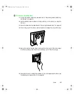
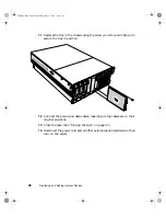
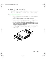
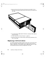
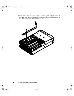
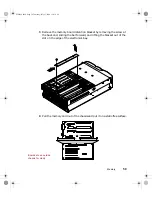
Align the drive rails with the grooves at the top and bottom of the
5.25-inch drive bay and slide the device into the bay until the rails click
into place.
7
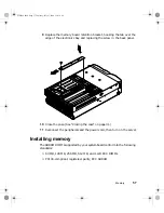
Connect power and data cables to the device, making sure the cables are
oriented correctly.
8
Close the case. (See “Closing the case” on page 31.)
9
Reconnect the power cord and all other external peripheral devices, then
turn on the server.
Replacing a 5.25-inch device
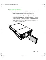
The chassis supports a single half-height 5.25-inch device. The 5.25-inch drive
bay is in the center of the front panel. If you remove a device from the
5.25-inch drive bay, you must either install a replacement device or install
the metal EMI shield that originally shipped with the server.
8506284.book Page 50 Thursday, July 13, 2000 11:43 AM
Summary of Contents for 8450R
Page 1: ...A MAN US 8450R SYS GDE R0 6 00 8450R Server System Manual ...
Page 5: ...iv 8506284 book Page iv Thursday July 13 2000 11 43 AM ...
Page 19: ...18 System Features 8506284 book Page 18 Thursday July 13 2000 11 43 AM ...
Page 25: ...24 System Setup 8506284 book Page 24 Thursday July 13 2000 11 43 AM ...
Page 119: ...118 Using the BIOS Setup Utility 8506284 book Page 118 Thursday July 13 2000 11 43 AM ...
Page 147: ...146 Troubleshooting 8506284 book Page 146 Thursday July 13 2000 11 43 AM ...
Page 161: ...160 Safety Regulatory and Notices 8506284 book Page 160 Thursday July 13 2000 11 43 AM ...
Page 172: ...A MAN US 8450R SYS GDE R0 6 00 8450R Server System Manual ...

