background image

G4-304SD1a


User Manual & Install Guide 


67 of 151    


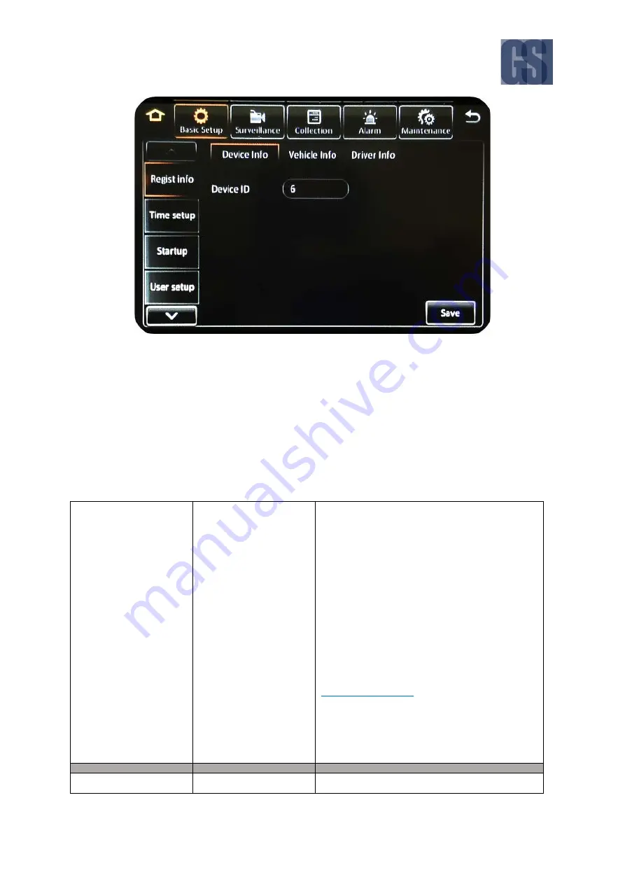
Figure 6-2 Basic Setup Tab in the Device Configuration Options 


6.3.1


Regist Info 

Navigate to: 

Main Menu 

 Setup 

 Basic Setup 

 Regist Info


This subsection enables you to view and set the various identification codes to be associated with the 

device, as well as the vehicle it will be installed in, and the associated vehicle driver. 


Device Info 

Device ID 

Numeric  text  field for setting a number to 

identify the device.  
 
You may input up to a maximum of: 


5 digits 


Note: 

-


This value is only set when the device is 
configured as part of a Gatekeeper Wireless 
deployment. 


DEFAULT SETTINGS: 
Please refer to Gatekeeper Project Team, in 

consultation with customer/school district, for 

the value to set. 


Vehicle Info 

Vehicle Plate 

.

 Alphanumeric text field for setting the vehicle 

Summary of Contents for G4-304SD1a

Page 1: ...G4 304SD1a User Manual Install Guide Document Ref No DN2981 Version No 1 0 0 Document Date 19 th July 2017 Fleet Safety Security and Tracking Solutions TM ...

Page 2: ... STATUS INFORMATION 26 3 6 LOGGING INTO THE SYSTEM 29 3 7 UNDERSTANDING THE MAIN MENU 31 4 BASIC SYSTEM QUICK START 33 4 1 STEP 1 POWERING UP THE G4 304SD1A 33 4 2 STEP 2 CONNECTING YOUR NAVIGATION DEVICE 33 4 3 STEP 3 LOGGING IN AND ACCESSING SYSTEM CONFIGURATION 34 4 4 STEP 4 SETTING THE DATE AND TIME 37 4 5 STEP 5 SETTING THE VEHICLE IDENTITY INFORMATION 38 4 6 STEP 6 SETTING BASIC PREFERENCES ...

Page 3: ...128 6 6 2 Filedata 129 6 6 3 Upgrade 130 6 6 4 Storage 131 6 6 5 Reset 131 6 6 6 Hardware 131 7 SPECIAL TOPICS 133 7 1 SETTING UP AN IP CAMERA 133 7 1 1 Adding an IP Camera 133 7 2 CONFIGURING SUBSTREAM RECORDING QUALITY 134 7 3 USING A NEW SD CARD 137 7 4 SEQUENTIAL RECORDING REQUIRES TWO SD CARDS 138 7 5 UPGRADING DEVICE FIRMWARE 139 8 MAINTENANCE AND TROUBLESHOOTING 140 9 HARDWARE INSTALLATION ...

Page 4: ...ntrols 48 Figure 5 4 REC Search Camera Channel Controls 49 Figure 5 5 REC Search Time Controls 50 Figure 5 6 REC Search Playback Controls 52 Figure 5 7 Log Search Date Controls 58 Figure 5 8 Log Time and Type Selection 59 Figure 5 9 View and Export Log File 60 Figure 6 1 Layout of the Configuration Menu 63 Figure 6 2 Basic Setup Tab in the Device Configuration Options 67 Figure 6 3 Surveillance Ta...

Page 5: ...oding MPEG 4 AVC this is a video coding format that is currently one of the most commonly used formats for the recording compression and distribution of video content ICD ICD2 Interactive Control Display purpose built touch screen monitors for operating Gatekeeper Systems G4 304SD1a IO Input Output IP Camera An Internet protocol camera or IP camera is a type of digital video camera commonly employ...

Page 6: ...rantees that packets will be delivered in the same order in which they were sent UDP UDP is a simple connectionless transmission model with a minimum overhead of protocol mechanisms USB Universal Serial Bus it is an industry standard that defines the cables connectors and communications protocols used in a bus for connection communication and power supply between computers and electronic devices U...

Page 7: ...llowing pages are intended to prevent injury to yourself and other persons or damage to the equipment Always ensure that the product is used correctly and in accordance with the listed instructions Be sure to also check the manuals included with any other product accessories that you may use SAFETY AND INFORMATION SYMBOLS USED IN THIS MANUAL This symbol is intended to alert the user to the presenc...

Page 8: ...wn The SD Card is specially formatted for use in your G4 304SD1a Please do not format it yourself using Microsoft Windows A SD card from a G4 304SD is not compatible with the G4 304SD1a and so would require to be formatted in the G4 304SD1a prior to use Prior to removing the SD card for viewing video on a pc it is essential that the G4 304SD1a be fully powered down before removal of the SD card Fa...

Page 9: ...s Indicators Status indicator lights which light up and or flash to alert the user to the device s operational status and or alarm status C USB Port Supports external USB flash drives which can be used for saving uploading configuration files updating system firmware and downloading of recorded video event files When not in use the port is covered by a port cover D SD Card Slot The SD Card is inst...

Page 10: ...re error NET Illuminated green indicates network connection is available Note The LAN LED status light is currently not supported Figure 2 3 Rear View of the G4 304SD1a A GPS Antenna In This is the connection point for the external GPS antenna If there is no GPS antenna attached this port should be covered with a rubberized cap B Analog and AHDcamera connectors C Serial Sensor cable CAB000376 conn...

Page 11: ...ital video recorder with a state of the art hard disk drive suspension system and smart thermal management technology Power Cable CAB000360 This is the vehicle power ignition cable for powering the G4 304SD1a and its connected accessories Sensor Cable CAB000376 This is the sensor cable for connecting the various sensor input to the G4 304SD1a Power Line Fuse Ignition Line Fuse Fastening Screws Fro...

Page 12: ...ntation that came with your computer system or speak with your I T department staff to determine if you have an internal SD reader and how to insert the SD card into your system If you are using and external SD card reader it is essential that the SD Card is inserted into the reader in the correct orientation or permanent damage may occur to the SD card the Card reader or both 1 Select the slot on...

Page 13: ...ing it Pressing the buttons on the IR Remote Control will then allow you to perform the selected action Finger Mouse FDM G51 This is a trackball mouse which enables access to the G4 304SD1a functions and menu system through a simple point and click interface The G4 304SD1a menu and navigation actions are displayed on the accompanying LCD monitor You will be able to move the on screen pointer using...

Page 14: ...the video stream from the corresponding camera Pressing the button zero 0 will cycle through the camera channels iteratively Increment Key This button provides a quick way to increase the parameter value by one unit in configuration screens Decrement Key This button provides a quick way to decrease the parameter value by one unit in configuration screens Main Menu This two buttons provide a quick ...

Page 15: ...G4 304SD1a User Manual Install Guide 15 of 151 How to Connect the IR Remote Control and LCD Monitor Connecting the IR Remote Control and LCD Monitor ...

Page 16: ...a finger operated mouse ball which moves the on screen mouse pointer in response to the movement of the track ball This is used to move the pointer to the left and right as well as up and down in order to point to a desired button or menu item Trigger Button Pressing this button will select the screen area button or menu item that the on screen pointer is currently pointed at Pressing and holding ...

Page 17: ...G4 304SD1a User Manual Install Guide 17 of 151 How to Connect the Finger Mouse and LCD Monitor Figure 3 2 Connecting the Finger Mouse and LCD Monitor ...

Page 18: ...en A single tap anywhere on the screen when showing video streams will bring up the on screen quick menu Another single tap anywhere on the screen will hide the quick menu again At all times tapping on an on screen field tab or button in the menu system will select it Tapping holding and dragging will also work for sliders and moveable items allowing you to perform click and drag actions Menu Key ...

Page 19: ...ny button from 1 9 will immediately jump to the video stream from the corresponding camera Pressing the button zero 0 will cycle through the camera channels How to Connect the ICD2 Figure 3 4 Connecting the ICD2 If using an ICD2 CP4 you must first configure the DVR for it First plug the 4 Pin Female Aviation end of CAB000390 into the A V output on the back of the unit also 4 Pin Male Aviation Next...

Page 20: ...e the cursor using Arrow Keys until the desired text field is highlighted then press the Enter Key An on screen keyboard will be displayed Type your text by moving the cursor with Arrow Keys to highlight each letter and pressing the Enter Key Move the on screen pointer using the Track Ball until it is situated over the text field then click the Trigger Button An on screen keyboard will be displaye...

Page 21: ...ng your finger 7 Go back to previous screen Press the Exit button on the IR Remote Not applicable Use the on screen controls Press the Exit button on the ICD2 8 Display the on screen quick menu Note On screen quick menu is only accessible from the live video view screens When you are at any live video view screen press the Exit button on the IR Remote to toggle between displaying and hiding the on...

Page 22: ...en controls Press the 0 button on the numeric keypad of the ICD2 12 Playback controls for video When you are viewing video playback press the Setup key to display hide the on screen video playback controls which you then use to adjust the video playback Besides that you may also use the following dedicated keys on the IR Remote to perform the following actions Pause Step through the video frame by...

Page 23: ... being used along with a Finger Mouse or IR Remote control This ensures that the user always has a familiar interface and consistent methodology to interact with the menu system and device functions Figure 3 5 G4 304SD1a Startup Screen Live Video From Cameras By default upon system startup the screen will display live video from the camera attached to channel one in single camera full onscreen vie...

Page 24: ...he system will display the login screen Playback Function This opens up the recorded video playback screen This function requires the user to be logged in If the user is not logged in yet the system will display the login screen 3 4 Viewing Live Video Single Camera On screen View When the screen is in Single Camera On screen View mode camera from a single camera channel will be shown on the entire...

Page 25: ...quad grid display mode by pressing the key zero 0 on the ICD2 9 Camera On screen View In 9 Camera On screen View mode the screen is split into nine sections using a 3x3 grid layout and video from all connected cameras is simultaneously shown on the screen Note all other areas will display a black box In order to select a specific camera for viewing you may press any of the keys 1 5 on the ICD2 to ...

Page 26: ...formation active modules server status environment data and storage size Figure 3 8 System Information Function on Quick Menu This System Information function is a quick and easy way to access and view all the important information about your device s status and configuration from one central location It can be accessed directly from the on screen quick menu without the need to log in The followin...

Page 27: ... of the WiFi connection status of the device This includes information on whether WiFi is enabled the signal strength connection point and the IP address of the device The information shown is as follows Built in WiFi Status Signal Strength IP Address External WiFi Status ESSID IP Address 3 Modules Location Not supported by Gatekeeper This screen shows the GPS data giving the current device locati...

Page 28: ...nformation for different servers which are set up in the system 5 Environment This screen summarises the current environmental conditions of the device It shows the operating voltage device temperature in Celsius and whether the device s smart thermal management system is currently active The information shown is as follows Voltage Device Temperature C HDD Heater Status 6 Storage This screen lists...

Page 29: ...nd the following functions REC Search Log Search Setup this function requires the user to be logged in as an administrator How to Log In When attempting to access any of these functions the system will check the log on status of the user before granting access to the function If the user is not already logged in the system will automatically prompt the user to log in Step 1 System will display the...

Page 30: ...ny time you may also cancel the log in process by clicking the Cancel button Notes The system ships with the following two default user credentials User name admin default administrator account Password admin User name user Password user You may change the default administrator user password and also edit add additional users through the user management function in the configuration settings Norma...

Page 31: ...Main Menu can be accessed by clicking the Person icon on the far right of the on screen quick menu Figure 3 8 Accessing the Main Menu The Main Menu has five options as shown in the following figure Figure 3 9 Options in the Main Menu REC Search Search for view and save recorded video ...

Page 32: ...es Setup View and make changes to the device configuration options Logout Logout the current logged in user This will return the system to the live video view The REC Search and Log Search functions will be explained in the chapter on Viewing Recorded Data whilst the Setup function will be explained in the chapter on Configuring the G4 304SD1a ...

Page 33: ...s from years of experience If you prefer to mount the device yourself please read Chapter 9 for detailed hardware installation instructions Turning your vehicle ignition on will automatically power up the G4 304SD1a When your vehicle ignition is turned off the device will automatically shut down after 5 minutes you will be able to change this later in the device settings 4 2 Step 2 Connecting your...

Page 34: ...Mouse click the Right Button whereas ICD2 users can just tap on the screen On the quick menu click the Person icon This will prompt you to login to the system Step 3 2 System will display the log in dialog box as shown below Ensure that admin is displayed in the User Name field If not then click on the drop down v button at the right corner of the User Name field A drop down list of user names wil...

Page 35: ...e you will be able to tailor almost every aspect of the device operations to your unique fleet requirements The configuration options in the menu are broken into 5 major sections Basic where you will be able to configure all the basic device preferences and operational settings For a detailed explanation please see Section 6 3 Surveillance where you will be able to configure camera viewing recordi...

Page 36: ...nd firmware upgrades For a detailed explanation please see Section 6 7 Each of these major configuration sections have their separate subsections as shown in the following diagram Figure 4 2 Setup Menu System for Device Configuration For the basic setup process we will just need to verify and or configure the settings in the subsections highlighted with the red dotted lines in the diagram as follo...

Page 37: ... 2 General Date Format DEFAULT SETTINGS MONTH DAY YEAR Time Format DEFAULT SETTINGS 24 Hours Time Zone DEFAULT SETTINGS GMT 08 00 PACIFIC TIME US CANADA If this is not your time zone please change this setting as appropriate to the actual time zone that your fleet will be operating in Time Sync Date Time DEFAULT SETTINGS Please verify the time and date If the time and or date is not correct please...

Page 38: ...ort generation and tracking purposes Navigate to Main Menu Setup Basic Setup Regist Info Please key in the vehicle and driver information of the vehicle that this device is mounted in For a detailed explanation of each setting please see Section 6 3 1 Device Info Device ID Leave this value as it is unless directed to change by Gatekeeper Project Team Vehicle Info Vehicle Plate You can use this fie...

Page 39: ...es Next you will need to setup the ignition on off delay time Navigate to Main Menu Setup Basic Setup Startup Please verify that the following default settings are correctly configured For a detailed explanation of each setting please see Section 6 3 3 ON OFF ON OFF Mode DEFAULT SETTINGS Ignition Ignition Delay DEFAULT SETTINGS 300 This means that when the vehicle is turned off the device will con...

Page 40: ...ting Up Authorised Users Next you can add additional user login accounts to the device if required Navigate to Main Menu Setup Basic Setup User Setup Your G4 304SD1a comes pre configured with the following two default user accounts Default administrator user Username admin Password admin Default normal user Username user Password user It is highly recommended that you do not change the password on...

Page 41: ... the recorded video Navigate to Main Menu Setup Surveillance Record Please review and adjust the following default settings to match your actual camera configuration For a detailed explanation of each setting please see Section 6 4 2 General System DEFAULT SETTINGS NTSC Overwrite DEFAULT SETTINGS By Capacity Lock Duration DEFAULT SETTINGS 7 days Pre Recording DEFAULT SETTINGS Checkbox Unselected M...

Page 42: ...era channel only enable this channel if it actually has a camera connected Resolution DEFAULT SETTINGS For channels 1 to 4 analog camera channels set the following D1 For channels 5 IP camera channel set the following 720P Frame Rate DEFAULT SETTINGS For all channels 1 to 12 set the following 15 Quality DEFAULT SETTINGS For all channels 1 to 5 set the following 1 Best Record Mode DEFAULT SETTINGS ...

Page 43: ... DEFAULT SETTINGS For channels 1 to 4 analog camera channels set the following Checkbox Unselected For channels 5 IP camera channel set the following Checkbox Unselected OSD Time DEFAULT SETTINGS Checkbox Selected Vehicle Plate DEFAULT SETTINGS Checkbox Unselected Channel Name DEFAULT SETTINGS Checkbox Selected Speed DEFAULT SETTINGS Checkbox Selected GPS DEFAULT SETTINGS Checkbox Selected Device ...

Page 44: ...connected physically it will need to be configured in the system before it will work Navigate to Main Menu Setup Surveillance IPC Setup Please follow the steps in Section 6 4 3 to setup the IP Camera in your system 4 10 Step 10 Finish Your new G4 304SD1a system is now setup and ready to go Please also review Chapter 5 to learn about viewing and clipping the recorded video ...

Page 45: ...screen single camera channel or in quad view four camera channels simultaneously In order to access single camera playback please click the Playback button while in Single Camera On screen View Besides using the and on screen buttons to cycle between channels they can also be directly selected using the buttons 1 5 E g Press 3 for channel 3 In order to access quad camera playback please click the ...

Page 46: ...enu will be displayed whereas if you are in video playback mode then the playback on screen controls would be displayed instead Figure 5 2 Playback On Screen Controls Time Bar This time bar represents the entire day from 00 00 00H to 23 59 59H Recorded Video Available The green shaded areas in the time bar lets you easily identify time periods during the day where recorded video is available Slide...

Page 47: ...l cycle the reverse playback speed iteratively through the following speed settings 2x 4x 8x and 16x Play Pause Clicking this button will toggle the video between playback and pause If the video is playing in either fast forward or reverse play direction then clicking this button will revert to forward playback in real time speed 1x Forward Play Clicking this button will cycle the forward playback...

Page 48: ...you to select a date to view the recorded video It uses a calendar view to enable the user to easily visualise the availability of recorded video and also employs color coding to provide easy identification of dates for which the recorded video has special characteristics e g locked video or alarm events What is locked video The device setup allows you to configure the recording settings such that...

Page 49: ...corded video whether from the Main Record Sub Record or Mirror Record By default it always searches from the Main Record first Select Month The and v buttons allow you to scroll through and select the month Select Year The and v buttons allow you to scroll through and select the year Calendar View The calendar shows the dates for the month and year which has been selected Clicking on the date of i...

Page 50: ...ls are marked with a red check Recorded video will only be retrieved for playback from the selected camera channels Search After selecting the video type and camera channels clicking on the Search button will proceed to the playback screen for the recorded video REC Search Step 3 Selecting the Time Period After the date and camera channels have been selected the time period display screen allows y...

Page 51: ... Use the checkboxes to select deselect the camera channels which are to be included in the playback Scroll Camera Channels When more than four camera channels have recorded video available click the and v buttons to scroll up and down in the list of available channels Recorded Video Available The colored bar shows the times for which recorded video is available The bar is colored coded to indicate...

Page 52: ...an toggle the on screen controls by pressing the Right Button whereas with the ICD2 you would just tap anywhere on the video If there is no user input then the on screen playback controls will auto hide after 15 seconds of inactivity If more than one camera channel was selected for playback during the previous step all the selected channels will be displayed in quad screen mode 2x2 grid layout Wit...

Page 53: ... clicking this button will switch to playing recorded video from Camera 4 Cycle to Previous Channel Switch playback to the previous camera channel For example if the system is currently playing recorded video from Camera 3 then clicking this button will switch to playing recorded video from Camera 2 Reverse Play Clicking this button will cycle the reverse playback speed iteratively through the fol...

Page 54: ...ded Video At the time period selection screen of the REC Search function you may also choose to export a video clip of the recorded video data by specifying a start and end time for the video and clicking the Export button on the screen At any time you may return to the previous screen by clicking or the Back button You can also click the Home icon to return to the Main Menu How to Perform the Exp...

Page 55: ... if the available space on the selected external storage medium must be equal or more than the estimated file size Please Note If you are using the Finger Mouse LCD combination to navigate you will need to use a Gatekeeper Systems USB Hub to allow two devices to share the one USB port You will also need to select the file format that the exported video clip will be saved as Proprietary Data File f...

Page 56: ... as the desired start time Your selection will be displayed on the screen Next select the desired end time by once again clicking on the time and keying in or moving the marker as before When your desired end time is displayed click the End Time button to register this Your selected end time will be displayed on the screen The system will calculate and display the estimated file size of the video ...

Page 57: ...eeper Systems AVI Data Standard AVI file format Can be viewed using any standard media player Click the Export button to proceed to clip and save the video data to the specified external storage device If you wish to go back at any time to select a different time period you may click the Cancel button 5 3 Using Log Search The Log Search feature can be accessed from the Main Menu after logging in I...

Page 58: ...ons allow you to scroll through and select the month Select Year The and v buttons allow you to scroll through and select the year Calendar View The calendar shows the dates for the month and year which has been selected Clicking on the date of interest will select it Next Step After selecting the date clicking on the Next button will proceed to the camera channel selection screen Log Search Step ...

Page 59: ...t Select Log Type This allows you to select the type of log file to be displayed Alarm Log file listing alarm events Operation Log file listing operational events Locked Log file listing locked events What are locked events The device setup allows you to configure the recording settings such that video is always retained for a specified number of days after it is recorded Locked video refers to re...

Page 60: ...on allows you to view the log file data and to export it to an external storage device for archival or later study Figure 5 9 View and Export Log File Main Menu Click this icon to return to the Main Menu Back to Previous Screen Click this icon to return to the Previous Screen that you were at Page Up Down The and v buttons allow you to scroll the pages of the log data Jump to Page Clicking on the ...

Page 61: ...G4 304SD1a User Manual Install Guide 61 of 151 Export Clicking this icon allows you to export the log file to an external storage USB flash drive ...

Page 62: ...r a detailed description of each section 6 2 Navigating the Configuration Menus The configuration menus are presented in a tabular format where the main sections can be selected from the row of tabs at the top of the screen The subsections within each main section are arrayed in columnar format and can be selected from the column of page subsections on the left edge of the screen Within each subse...

Page 63: ...ay the configuration settings related to this particular subsection Scroll Up Click this button to scroll up in the list of subsections Scroll Down Click this button to scroll down in the list of subsections Nested Sub Tabs in Page Some subsection pages will also have nested sub tabs to further subdivide the configuration settings Click on the sub tab to open the related settings page Scroll Page ...

Page 64: ...ton will either perform an action or advance you to the next step in the process Checkbox Checkboxes allow you to toggle an item clicking on it will select it and clicking on a selected item will deselect it If the checkbox is checked has a checkmark in the box then the item next to the checkbox is selected An empty box no checkmark means the item is not selected Multiple selections are allowed Ra...

Page 65: ...an on screen keypad for the user to key in numeric values Date Field This is an input field for dates Clicking on this field will show a calendar from which the user can select the desired date Time Field This is an input field for time Clicking on this field will show an on screen keypad which the user can use to enter the time values ...

Page 66: ...licking this button will display a list of items which can be scrolled and selected 6 3 Basic Settings Navigate to Main Menu Setup Basic Setup All the core device settings can be configured in this section This includes key operational configurations such as device identifiers and vehicle information user management time setup device startup behaviour and communications setup such as network setti...

Page 67: ...as the vehicle it will be installed in and the associated vehicle driver Device Info Device ID Numeric text field for setting a number to identify the device You may input up to a maximum of 5 digits Note This value is only set when the device is configured as part of a Gatekeeper Wireless deployment DEFAULT SETTINGS Please refer to Gatekeeper Project Team in consultation with customer school dist...

Page 68: ...ut up to a maximum of 10 characters DEFAULT SETTINGS Please refer to Gatekeeper Project Team in consultation with customer school district for the value to set Line Number Alphanumeric text field for setting the vehicle line number This is typically the identification code used by the fleet operator to identify a particular route You may input up to a maximum of 10 characters DEFAULT SETTINGS Plea...

Page 69: ...or the value to set 6 3 2 Time Setup Navigate to Main Menu Setup Basic Setup Time Setup The device contains a real time clock This subsection enables you to view and set the date and time for the device and also configure the options used for time synchronization as well as daylight savings General Date Format Drop list which allows you to choose the format in which date values will be displayed M...

Page 70: ... Date field which enables you to set the current date Time field which enables you to set the current time Drop list which allows you to choose AM PM only applicable if Time Format is set to 12 Hours DEFAULT SETTINGS Please verify the time and date If the time and or date is not correct please change them to the correct values Satellite Checkbox if selected the device will synchronize the date and...

Page 71: ...l synchronize the date and time periodically with a selected Time Server If this option is selected you will also need to use the associated drop list to specify which Time Server will be used for the time synchronization Note This setting requires a constant network connection either via cellular or WiFi DEFAULT SETTINGS Checkbox Unselected DST Enable Checkbox selecting this will enable the devic...

Page 72: ...T SETTINGS Week Start This is a set of fields which allow you to choose the starting point of the period for which the device will adjust for daylight savings time If the device is adjusting for daylight savings by Week you will need to specify the following Drop list to choose the start month from JAN to DEC Drop list to choose the start week either 1 ST 2 ND 3 RD 4 TH or LAST Drop list to choose...

Page 73: ...to choose the end time If the device is adjusting for daylight savings by Date you will need to specify the following Date field to set the end date Time field to set the end time DEFAULT SETTINGS NOV month 1ST week SUNDAY day 02 00 00 time 6 3 3 Startup Navigate to Main Menu Setup Basic Setup Startup This subsection enables you to set the startup characteristics of the device as well behaviour of...

Page 74: ...The device will only stop recording and shutdown after this delay period is past DEFAULT SETTINGS 300 This means that when the vehicle is turned off the device will continue to record for another 300 seconds 5 minutes before shutting down Timer From This consists of two time fields to set the start time and end time for which the device will turn on and turn off respectively Light off time DEFAULT...

Page 75: ... be consistently below this threshold value For a vehicle with a 12V battery the recommended threshold value is 9V For a vehicle with a 24V battery the recommended threshold value is 21V DEFAULT SETTINGS Disabled not applicable Voltage Startup Numeric text field to set the recovery boot voltage threshold When the vehicle battery recovers its charge and is consistently above this threshold value th...

Page 76: ...r the specified period of inactivity 30 Seconds 1 Minute 3 Minutes 5 Minutes 10 Minutes Never DEFAULT SETTINGS 3 Minutes User Name User Group The User Name shows the list of users who are set up in the system The User Group shows the type of user Checkboxes next to the user names allow you to select the specified user to edit or delete Notes The user admin is the default administrator and cannot b...

Page 77: ...or password you may input up to a maximum of 16 characters Delete After using the checkbox to select a user this button will allow you to delete the selected user A confirmation message will be displayed clicking the Yes button on this prompt will confirm the action and proceed to delete the selected user from the device Edit After using the checkbox to select a user this button will display the e...

Page 78: ...ay automatically from the DHCP server DEFAULT SETTINGS Checkbox Unselected Static IP Checkbox if selected the device will use the manually configured IP Address Subnet Mask and Gateway DEFAULT SETTINGS Checkbox Selected IP Address Numeric text field allowing you to key in the IP address for the device DEFAULT SETTINGS 192 168 088 002 Subnet Mask Numeric text field allowing you to key in the IP add...

Page 79: ...EFAULT SETTINGS 192 168 001 001 Alternate DNS Server Numeric text field allowing you to key in the IP address of the alternate DNS server DEFAULT SETTINGS 192 168 001 001 Ports WEB Port Numeric text field to set the web port number DEFAULT SETTINGS 80 NOTE THE FOLLOWING SECTION WIFI IS ONLY APPLICABLE FOR G4 304SD1a EQUIPPED WITH THE INTERNAL WIFI MODULE GATEKEEPER DOES NOT SUPPORT THIS CONFIGURAT...

Page 80: ...s DEFAULT SETTINGS Disabled not applicable Static IP Checkbox if selected the device will use the manually configured IP Address Subnet Mask and Gateway Else it will attempt to automatically obtain these values DEFAULT SETTINGS Disabled not applicable IP Address Numeric text field allowing you to key in the IP address for the device DEFAULT SETTINGS Disabled not applicable Subnet Mask Numeric text...

Page 81: ...w you to modify them These configuration values are module specific If you have more than one communications module connected you will need to select each in turn and configure them separately DEFAULT SETTINGS Disabled not applicable Server Type This field is for display only It automatically displays the service type for the selected module if it is connected to the service provider If not connec...

Page 82: ...configure the password DEFAULT SETTINGS Disabled not applicable Number Numeric text field allowing you to configure the dial up number DEFAULT SETTINGS Disabled not applicable Certification Drop list allowing you to configure the authentication protocol CHAP PAP DEFAULT SETTINGS Disabled not applicable Active Mode Drop list allowing you to configure the active mode settings Always Phone SMS Sensor...

Page 83: ... list of center servers configured in the device Selecting one of them will display the currently set configuration values and allow you to modify them These configuration values are server specific If you have more than one center server set up you will need to select each in turn and configure them separately Add this button allows you to add a new center server name and configure its settings D...

Page 84: ...ULT SETTINGS N9M Enable Network Drop list to select the network mode used to communicate with the selected center server Local WiFi Not Supported Module1 Not Supported Module2 Not Supported DEFAULT SETTINGS Local Register Server Add Numeric text field to configure the IP address of the register server DEFAULT SETTINGS 174 1 68 160 Register Port Numeric text field to configure the port values used ...

Page 85: ...CP UDP DEFAULT SETTINGS TCP 8081 UDP 6111 6 3 6 Application Navigate to Main Menu Setup Basic Setup Application This subsection enables you to view and edit the application settings of the device related to FTP and traffic management NOTE GATEKEEPER DOES NOT SUPPORT THIS CONFIGURATION Download Auto download Reconnect Checkbox if selected the device will use the configured settings This item is uns...

Page 86: ...s for when recording actually takes place and adjust the resolution and quality of the recorded video Figure 6 3 Surveillance Tab in the Device Configuration Options 6 4 1 Live View Navigate to Main Menu Setup Surveillance Live View This subsection enables you to configure the settings for the live view of the video coming from the cameras These settings only affect the video being viewed on the L...

Page 87: ...lick and drag the respective slider bar knob to adjust the setting quickly There are 4 image color settings which can be adjusted BRI Brightness CON Contrast COL Color Warmth SAT Color Saturation Channel Being Configured This drop list enables you to select a channel to configure The video from the selected channel will be displayed and you will be able to adjust the settings Each channel can have...

Page 88: ... any changes unless you first save the settings Margins This button displays the margin setup screen which has the following options Margin top Margin bottom Margin left Margin right You may use the and buttons or click and drag the slider knob to adjust the margins of the screen to fit the display within the limitations of your display monitor This is especially useful if you find that parts of t...

Page 89: ... as a black box DEFAULT SETTINGS Checkbox Channel 1 Selected Checkbox Channel 2 Selected Checkbox Channel 3 Selected Checkbox Channel 4 Selected Checkbox Channel 5 Unselected Auto Loop Screen Mode Channel Duration Setup This displays a list of screen layouts which have been configured in the device If Auto Loop is enabled each of the screen layouts be displayed for the specified duration and the d...

Page 90: ... available grid segments then those segments associated with an actual camera will be displayed as a black box The drop down list will show for all connected cameras Duration This numeric text field allows you to specify the duration in seconds for which this layout will be displayed on the screen Save Settings The OK button allows you to save the settings for this screen layout Back to Previous T...

Page 91: ... identifier data which is set in the Basic Setup Regist Info Vehicle Info Vehicle Plate DEFAULT SETTINGS Checkbox Unselected Alarm Checkbox if selected any alarms will be displayed as an overlay text on top of the live video view on the LCD monitor or ICD2 DEFAULT SETTINGS Checkbox Selected Vehicle num Checkbox if selected the vehicle num will be displayed as an overlay text on top of the live vid...

Page 92: ...D monitor or ICD2 DEFAULT SETTINGS Checkbox Unselected 6 4 2 Record Navigate to Main Menu Setup Surveillance Record The G4 304SD1a is a hybrid DVR It has the capability of having a combination of analog analog HD and a single IP camera connected at the same time Please Note that the cameras if using a combination of analog and analog HD cameras must be used in pairs e g CAM 1 and CAM 2 Analog or C...

Page 93: ...written by newer video data in First In First Out FIFO format Never video will never be overwritten In order to ensure that the device still has storage to record new video you will have to download and remove the older video on a regular basis DEFAULT SETTINGS By Capacity Lock Duration Numeric text field setting the lock duration for video data If the lock duration is set then video will always b...

Page 94: ...nel Channel Name Alphanumeric text field for setting the channel name This is useful for giving the channel an easily remembered and or location specific name You may input up to a maximum of 5 characters Notes Channels 1 to 4 are analog channels Channel 5 is a Digital IP camera channel DEFAULT SETTINGS Channel 1 set name as CH1 Channel 2 set name as CH2 Channel 3 set name as CH3 Channel 4 set nam...

Page 95: ...y attached IP camera Most commonly these will typically be 720P 1280x720 DEFAULT SETTINGS For channels 1 to 4 analog camera channels set the following D1 For channel 5 IP camera channel set the following 720P Frame Rate Drop list allowing you to select the frame rate in terms of frames per second that you would like to record at DEFAULT SETTINGS For all channels 1 to 5 set the following 15 Quality...

Page 96: ... which allows you to set the starting time to begin the recording End Time this is a time field which allows you to set the ending time to stop the recording Video Type this is a drop list which allows you to select the type of video to be record either Normal video or Alarm video only x you can always click the x button to remove the associated recording task from the list Copy To this feature al...

Page 97: ...ensuring consistent quality and predictable file size of the recorded video When using VBR the device will vary the bit rate according to the level of detail in the video at each given point in time thus attempting to optimise quality against file size However for critical video where detail must not be lost and which also has a lot of fast movement CBR is the better choice as VBR would tend to in...

Page 98: ...edized external SD accessory called FireBox which is shock and fire resistant to keep a copy of your data safe in case of a vehicle crash or other catastrophic event so that video of the incident can be retrieved for post mortem analysis Please contact your Gatekeeper Systems sales representative for more details DEFAULT SETTINGS Internal SD Record Mode Drop list where you can select the dual stre...

Page 99: ...e Substream Setup screen Channel drop list to select the particular channel to configure When a channel is selected the corresponding recording settings for that channel will be displayed for viewing and editing Enable checkbox if selected would enable the substream recording for this channel If unselected would mean that video from this channel would not be recorded and stored as part of the subs...

Page 100: ... to save the current settings for the channel Cancel click this button to exit back to the previous screen without saving DEFAULT SETTINGS For all channels 1 to 5 set the following Enable Checkbox Selected Audio Checkbox Selected Resolution CIF Frame Rate 15 Quality 3 Mirror CH Checkbox select each checkbox to include the associated camera channel into the dual stream recording DEFAULT SETTINGS Fo...

Page 101: ...SETTINGS Checkbox Selected Channel Name Checkbox if selected the channel name will be displayed as an overlay text on top of the recorded video DEFAULT SETTINGS Checkbox Unselected Speed Checkbox if selected the speed will be displayed as an overlay text on top of the recorded video DEFAULT SETTINGS Checkbox Selected GPS Checkbox if selected the GPS coordinates will be displayed as an overlay text...

Page 102: ...g screen DEFAULT SETTINGS Checkbox Unselected Text Data Overlay The selected data is displayed as a text overlay on top of the video Moving the Text Data The position of the text data can be easily customised by moving it to the desired location In order to move it just tap or click on the text and then drag it to the desired location Revert to Defaults Clicking the Default button will revert all ...

Page 103: ... Setup Screen Camera Channels The available camera channels are listed on the screen along with their associated settings Please Note On a G4 304SD1a there is only One IP camera channel channel 5 Scroll Page Use the and v buttons to scroll the list of camera channels up and down respectively Enable Channel The checkbox toggles the camera between enabled and disabled Outside Channel This checkbox m...

Page 104: ...d the camera to the selected channel At any time you may click the Refresh button to re scan and update the list You may also click on Cancel to return to the previous screen Edit Channel Click on the button to edit the settings for the IP camera which is bound to that associated channel This displays a pop up screen with the settings that you can configure Figure 6 5 4 IP Camera Settings Configur...

Page 105: ...e to Main Menu Setup Collection This section allows the user to configure all the settings related to data collection This includes event logging from sensor input as well as alarms The user can also configure the options for automated snapshots from the cameras based on specified triggers Figure 6 6 Collection Tab in the Device Configuration Options 6 5 1 General Navigate to Main Menu Setup Colle...

Page 106: ...anumeric text field for setting a friendly name to easily identify the sensor You may input up to a maximum of 8 characters OSD Name Alphanumeric text field for setting a short code name identifying this sensor on the OSD text data overlay on the video You may input up to a maximum of 5 characters Sensor Uses This feature allows you to easily copy the configuration settings for this sensor to anot...

Page 107: ... Sensor Name RIGHTTRN OSD Name RT Sensor Number 7 Sensor Name EXTRA1 OSD Name EX1 Sensor Number 8 Sensor Name EXTRA2 OSD Name EX2 Serial Port RS232 1 The first associated drop list allows the user to configure the port function None Extend Control Panel 485 Bus External GPS 3Axis Acc PTZ CP4 DEFAULT SETTINGS None The second associated drop list allows the user to set the baud rate for the port 480...

Page 108: ...st other parts of the world including Canada where the metric system is adopted will typically choose KM H DEFAULT SETTINGS MPH Source Drop list allowing the user to set the source for the speed measurement Satellite Pulse Notes If the measurement unit is set to Pulse you will also need to select the calibration mode and perform a manual calibration Pulse mode is currently unsupported and Gatekeep...

Page 109: ...bsection enables you to view and edit the triggers and settings for capturing snapshots Make sure to check mark the Time Snap option so as to be able to setup options Time Snap Time Snap Checkbox if selected this feature allows you to set up a schedule to capture snapshots using the cameras Clicking the Add button will add a snapshot schedule task to the displayed task list with the following sett...

Page 110: ... this drop list enables you to select the resolution for the snapshots Available options are CIF WCIF HD1 WHD1 D1 WD1 720P Quality this drop list enables you to select the quality of the snapshot on a scale of 1 to 8 where 1 is best Upload Type checkboxes which allow you to select whether the snapshots are to be uploaded to FTP and or Server Snap Numbers numeric text field to key in the number of ...

Page 111: ...nel is included when the G4 304SD1a performs the snap shots Resolution this drop list enables you to select the resolution for the snapshots Available options are CIF WCIF HD1 WHD1 D1 WD1 720P Quality this drop list enables you to select the quality of the snapshot on a scale of 1 to 8 where 1 is best Upload Type checkboxes which allow you to select whether the snapshots are to be uploaded to FTP ...

Page 112: ... included when the G4 304SD1a performs the snap shots Resolution this drop list enables you to select the resolution for the snapshots Available options are CIF WCIF HD1 WHD1 D1 WD1 720P Quality this drop list enables you to select the quality of the snapshot on a scale of 1 to 8 where 1 is best Upload Type checkboxes which allow you to select whether the snapshots are to be uploaded to FTP and or...

Page 113: ...ported Current Software Version Calibration Currently Unsupported GDSPlatelet Coefficient Mileage Currently Unsupported Coefficient Oil Currently Unsupported GDS Work Pattern Currently Unsupported Clear Statistical Currently Unsupported GDS Version Currently Unsupported Alarm Settings Navigate to Main Menu Setup Alarm All settings related to alarm events are contained in this section The user can ...

Page 114: ... Enable Checkbox if selected enables the device to monitor for overspeed events In case of speed exceeding the specified threshold this alarm will be triggered To set the volume to MUTE for this alarm go to Basic Setup Other Setup Voice Setup TTS should be set to zero DEFAULT SETTINGS Checkbox Unselected Alarm Type Drop list to select the classification level for the alarm Event Alarm DEFAULT SETT...

Page 115: ...ge setup screen This sets up the video display recording and snapshot options associated with this alarm The Linkage setup screen enables you to configure the following options Channel checkboxes which allow you to select any combination of the camera channels to be included in the display and recording Post Recording drop list which allows you to select the duration for which video will continue ...

Page 116: ...ted You can easily choose each individual camera channel to be displayed in the selected grid segment visually If you have less cameras than available grid segments then those segments associated with an actual camera will be displayed as a black box PB Alarm Duration numeric text field to set the duration of the video playback in seconds when the alarm occurs Alarm Snap checkbox if selected when ...

Page 117: ...ettings Back to Previous Click the Cancel button to return to the previous screen without saving Linkage Click the Setup button under Linkage to go to the Linkage setup screen This sets up the video display recording and snapshot options associated with this alarm The Linkage setup screen enables you to configure the following options Channel checkboxes which allow you to select any combination of...

Page 118: ...when the alarm occurs None Not displayed Single Display 1 camera Quad Display 4 cameras If Single 1x1 or Quad 2x2 display is selected the Setup button allows you to select the layout of the channels to be displayed on screen The drop lists are shown on screen accordingly to the grid layout mode selected You can easily choose each individual camera channel to be displayed in the selected grid segme...

Page 119: ...e device to monitor the associated IO input line for an alarm trigger DEFAULT SETTINGS BRAKE Checkbox Selected WARNING Checkbox Selected STOPARM Checkbox Selected DOOR Checkbox Selected LEFTTURN Checkbox Selected RIGHTTRN Checkbox Selected EXTRA1 Checkbox Unselected EXTRA2 Checkbox Unselected Alarm Type Drop list to select the classification level for the alarm Event Alarm DEFAULT SETTINGS For all...

Page 120: ...ng Post Recording drop list which allows you to select the duration for which video will continue to be recorded when the alarm is triggered Lock checkbox if selected will mark the recorded video associated with this alarm as locked video 3G Network checkbox if selected will enable alarm notification over the 3G network Linkage IO Output checkboxes if enabled the device will send a signal to the s...

Page 121: ... will take snap shots using the selected cameras DEFAULT SETTINGS Please choose the camera channels to display and record in the event of this alarm being triggered These settings would need to be determined by the customer client to match their specific business requirements 6 5 5 Driver Alert Button Setup A Driver Alert Panel is available as an optional accessory for the G4 304SD1a The Driver Al...

Page 122: ...en the alarm occurs Video Videoloss Checkbox if selected enables the device to monitor for videoloss events In case of videoloss detected on the specified camera channels this alarm will be triggered DEFAULT SETTINGS Checkbox Selected Alarm Type Drop list to select the classification level for the alarm Event Alarm DEFAULT SETTINGS Alarm Trigger Click the Setup button under Trigger to display the ...

Page 123: ... displayed Single Display 1 camera Quad Display 4 cameras If Single 1x1 or Quad 2x2 display is selected the Setup button allows you to select the layout of the channels to be displayed on screen The drop lists are shown on screen accordingly to the grid layout mode selected You can easily choose each individual camera channel to be displayed in the selected grid segment visually If you have less c...

Page 124: ...te window will appear for Motion detection setup In this window several options are available Select the channel on which you want the motion detection to be recorded The area setup button of the selected channel will display a grid pattern Select the area required to be covered by Motion detection Linkage Setup When the setup button is selected a separate window will appear with options with mult...

Page 125: ...anced This subsection enables you to set up the trigger for alarm events based on ACC input and also to define the actions that will be taken when the alarm occurs G Sensor Name Checkbox if selected enables the device to monitor for G Sensor trigger events In case of G Sensor exceeding the threshold values this alarm will be triggered DEFAULT SETTINGS Checkbox Unselected Alarm Type Drop list to se...

Page 126: ...ions associated with this alarm The Linkage setup screen enables you to configure the following options Channel checkboxes which allow you to select any combination of the camera channels to be included in the display and recording Post Recording drop list which allows you to select the duration for which video will continue to be recorded when the alarm is triggered Lock checkbox if selected will...

Page 127: ...ach individual camera channel to be displayed in the selected grid segment visually If you have less cameras than available grid segments then those segments associated with an actual camera will be displayed as a black box PB Alarm Duration numeric text field to set the duration of the video playback in seconds when the alarm occurs Alarm Snap checkbox if selected when the alarm occurs the device...

Page 128: ...les for easy configuration of multiple G4 304SD1a Please Note If you are using the Finger Mouse LCD combination to navigate you will need to use a Gatekeeper Systems USB Hub to allow two devices to share the one USB port Config Config File Export Click the Export button to export the entire device configuration settings to a file This file will be saved on an external storage device most commonly ...

Page 129: ... Time Start Time This consists of the following two input fields Date date field to select the start date of the specified time period Time time field to select the start time of the specified time period Notes Start time is only applicable if exporting data using the Export Time option End Time This consists of the following two input fields Date date field to select the end date of the specified...

Page 130: ...drive attached to the device USB port CP4 Upgrade Click the Upgrade button to retrieve the CP4 update from a file and apply it to the system You will need a compatible update file saved on an external storage device most commonly a USB flash drive attached to the device USB port IPC Upgrade Click the Upgrade button to retrieve the IPC update from a file and select the target IPC camera in order to...

Page 131: ...e on it Format Click the Format button format the associated storage device All data on that storage device will be erased 6 6 5 Reset Navigate to Main Menu Setup Maintenance Reset This subsection enables you to reset the G4 304SD1a Reset Default All Settings Click the Reset button in order to reset all settings on the device to their factory default values System Reboot Click the Reboot button in...

Page 132: ...lash drive attached to the device USB port Hardware Config Export Click the Export button to export the entire Hardware configuration settings to a file This file will be saved on an external storage device most commonly a USB flash drive attached to the device USB port General Super Buttons Unsupported by Gatekeeper Systems Reserved for future development ...

Page 133: ...rk In the G4 304SD1a though adding a new IP camera to the system can easily be done through the automated setup options available in the setup menu 7 1 1 Adding an IP Camera The steps below provide a quick guide to adding a new IP Camera to the system manually For a detailed discussion on the configuration options available please refer to Section 6 4 3 Step 7 1 1 1 Navigate to Main Menu Setup Sur...

Page 134: ...rom this screen Your new IP Camera is now configured and will stream video to the selected channel for viewing and recording 7 2 Configuring Substream Recording Quality When you choose to record the substream to a secondary storage device using the Sub Record option you can also choose a different set of quality settings to use for this substream recording To configure this first go to the Record ...

Page 135: ...ording Click the Setup button to set up the recording options for the substream Figure 7 2 Substream Recording Settings This substream recording settings configuration needs to be done for each individual camera channel separately The following options will be available for configuration ...

Page 136: ...solution options are QCIF 176x120 CIF 352x240 HD1 704x240 Choose Frame Rate drop list allowing you to select the frame rate in terms of frames per second that you would like to record at Choose Quality drop list allowing you to select the encoding quality on a scale of 1 to 8 where 1 is best Select Copy To Channel this feature allows you to copy the current channel s substream recording settings d...

Page 137: ... prior to removing the SD card else data corruption will occur To do this just insert the SD Card into the SD Card slot on the G4 304SD1a Then Navigate to Main Menu Setup Maintenance Storage Figure 7 3 Formatting a New Storage Medium Click the Format button next to the SD Card to format it for use in the device Please note that formatting any storage media will remove all the data stored on it If ...

Page 138: ...creases the available storage when two SD cards are in the DVR This feature is called Sequential Recording In order to enable Sequential Recording the 304SD11a must be configured as follows Navigate to Setup Surveillance Record Dual Stream Record storage Internal SD Record Mode Loop Record This will enable the DVR to sequentially record During the changeover phase from one SD card to the other the...

Page 139: ...ion to navigate you will need to use a Gatekeeper Systems USB Hub to allow two devices to share the one USB port Please follow the insertion process noted on the Gatekeeper Systems USB hub Then Navigate to Main Menu Setup Maintenance Upgrade Figure 7 4 Upgrading Device Firmware Click the appropriate Upgrade button next to the component that you wish to update Browse to the folder on your USB flash...

Page 140: ...ted 2 Wipe down the G4 304SD1a and cameras using a clean microfiber cloth 3 Check cables on the back of the G4 304SD1a to ensure they have not vibrated loose Make sure that the cables do not show signs of wear cracks etc If so contact your Gatekeeper Systems sales representative to arrange for replacements 4 Pull out the SD Card and check to ensure that the G4 304SD1a has been recording video It i...

Page 141: ...G4 304SD1a User Manual Install Guide 141 of 151 9 Hardware Installation 9 1 Quick Reference Guide for Installation ...

Page 142: ...illance IPC Setup To set Vehicle ID navigate to Basic Setup Regist Info Vehicle Info After setting the configurations with the SD Card inserted access the Setup menu Navigate to Setup Maintenance Storage to format the SD Card Please note non Gatekeeper branded SD cards may not function reliably If used non Gatekeeper branded SD cards must be formatted in the G4 304SD1a prior to use Start vehicle a...

Page 143: ...ories unless approved by Gatekeeper Systems The device is designed for interior use only Do not install in areas that are exposed to excessive moisture Mount the device in a location that has good airflow and is not subject to excessive heat cold variations Ensure that the device is mounted where it is not easily accessible by non authorized personnel Ensure that ALL provided Split Loom are used a...

Page 144: ...ectly to the battery from the fuse panel Sensor Cable The sensor cable CAB000376 connects to the connector marked SERIAL SENSOR on the back of the device The sensor portion of the cable is 5 metres sheathed together Wires are colour coded and labelled with its corresponding Sensor number There is a 4 pin flat Molex connector for attaching a Driver Alert Button or Alert Panel ICD The ICD connector ...

Page 145: ... 9 1 G4 304SD1a Fuse Connections 9 3 2 Cabling Diagrams Please refer to the following pages with detailed cabling diagrams for the different installation configurations of the G4 304SD1a 1 Cabling Diagram with Analog Cameras Only 2 Cabling Diagram with Analog and Digital IP Camera Figure 9 2 Basic Connection ...

Page 146: ...G4 304SD1a User Manual Install Guide 146 of 151 Figure 9 3 G4 304SD1a Wiring with Wireless ...

Page 147: ...nning through holes in sheet metal ceiling bulkhead etc must be protected with grommets Ensure included gasket is in place between dome base plate and mounting surface When installing multiple cameras mark camera harness wires so the school district knows which camera is front and back by looking at the marked Molex output connectors Important Notes Routing the Camera Harness GSWHC2N XX Always use...

Page 148: ...tapping screws to fix the camera base to the vehicle Step 5 Connect the Camera Ball Molex connector to the connector at the end of the camera harness Hold the Camera Ball firmly against the Base Plate with the Microphone pointing downwards Position Camera Collar D over Camera Ball C with the lens window centered in the arched cut away in the Camera Collar Step 6 Hold Camera Collar D securely while...

Page 149: ...ct with abrasive metal to prevent short circuits Wire Routing Camera harness to be connected through opening in base Use existing wire paths wherever possible eg radio speakers etc Avoid excessively tight bends especially around metal surfaces Always use grommets when routing through sheet metal holes Coil and tie off excess harness or tuck up into ceiling ...

Page 150: ...ct the products operation f d bili h h b l d difi d Gatekeeper Systems is not responsible for lost or missing video The warranty does not extend to repairs made necessary by normal wear or by the use of parts or accessories which are either incompatible with the Company product or adversely affect its operation performance or durability Gatekeeper Systems reserves the right to change or improve th...

Page 151: ...1Contact Information CONTACT INFORMATION GSI Canada 301 31127 Wheel Avenue Abbotsford BC V2T 6H1 Canada GSI USA 446 Harrison Street Sumas WA 98295 USA SALES TECHNICAL SUPPORT North America Tel 1 604 864 6187 Fax 1 604 864 8472 Toll Free 1 888 666 4833 ...

Reviews: