


www.gastron.com
10
_
11
GTC-520F
Instruction Manual
No
ITEMS
SPECIFICATION
1
Case cover
It fixes ALDC 040614 Main PCB and protects the circuit from surrounding environment and
external shock.
2
Case body
It fixes ALDC 040614 display and protects the circuit from surrounding environment and
external shock.
3
Marking label
It labels brief information such as model name, explosion-proof grade, etc.
4
Mount hole(2-Ø10)
It is a hole to fix the control unit to an external wall or other mount plate.
5
Concentration Display
(FND Digital Display)
It displays measurement from a detector connected to each channel in a continuous manner.
During test, it displays user defined value with flickering.
6
External Function Switch
"FUNC" S/W is a key to input data by changing and selecting threshold, type, dead band,
dwell, and etc. settings of the alarm. It is controlled externally using a magnetic bar.
7
External Test Switch
Pressing "TEST" S/W enters a mode that performs self-test.
Measurement FND flickers and the value can be adjusted using "TEST" S/W to check the
alarm operation status.
To release self-test, press buzzer stop and return switches. It is controlled externally using a
magnetic bar.
8
External UP Switch
After selecting each mode using "FUNC" S/W, it is used to increase the set value or to select
the next setting. To change setting value in a large range, pressing "UP" S/W for a certain time
changes the value rapidly.
It is controlled externally with a magnetic bar.
9
DOWN Switch
After selecting each mode using "FUNC" S/W, it is used to decrease the set value or to select
the previous setting. To change setting value in a large range, pressing "DOWN" S/W for a
certain time changes the value rapidly.
It is controlled externally with a magnetic bar.
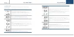
10
Power LED
When power is inputted, the power LED lights on.
11
Stand-by LED
When the detector is in stand-by mode, STD-BY LED blinks.
12
Trouble LED
When power is inputted, the power LED lights on.
When the detector is in stand-by mode, STD-BY LED blinks.
13
Alarm 3 LED
When the tertiary alarm occurs, Alarm 3 LED lights on.
When it reaches Alarm 3 threshold during a test, Alarm 3 LED lights on.
14
Alarm 2 LED
When the secondary alarm occurs, Alarm 2 LED lights on.
When it reaches Alarm 2 threshold during a test, Alarm 2 LED lights on.
15
Alarm 1 LED
When the primary alarm occurs, Alarm 1 LED lights on.
When it reaches Alarm 1 threshold during a test, Alarm 1 LED lights on.
16
Buzzer
Operates in a continuous tone upon an event of warning or fault during a test.
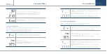
17
External POWER Switch
S/W used to turn ON and OFF of the control unit power. When performing cable wiring work,
power must be turned OFF.
18
External Buzzer Stop /
Return Switch (Ack & Reset)
Used to stop the buzzer upon an event of A alarm Performs functions to release alarm, self-
test, and program setting, etc.
19
Internal Power
ON/OFF Switch
S/W used to turn ON and OFF of the control unit power. When performing cable wiring work,
power must be turned OFF.
20
Power Input Terminal
Terminal for power cable connection for operation of the control unit.
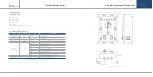
No
ITEMS
SPECIFICATION
21
External Warning Light
Power Terminal
Assistance power terminal for installation of external warning light during operation of the
control unit.
22
Signal I/O terminal
Used for connecting cables for power supply of gas leak detector, 4~20 mA current output,
and RS-485 MODBUS Network, etc.
23
Signal output terminal
Used for Relay Dry Contract Signal such as warning, failure, etc. and connecting Switch
Signal Output Cable, etc.
24
Power Input Terminal
Terminal for power cable connection for operation of the control unit.
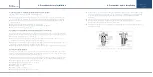
25
Internal UP Switch
After selecting each mode using "FUNC" S/W, it is used to increase the set value or to select
the next setting. To change setting value in a large range, pressing "UP" S/W for a certain
time changes the value rapidly.
It is controlled externally with a magnetic bar.
26
Internal DOWN Switch
After selecting each mode using "FUNC" S/W, it is used to decrease the set value or to select
the previous setting. To change setting value in a large range, pressing "DOWN" S/W for a
certain time changes the value rapidly.
It is controlled externally with a magnetic bar.
27
Internal Function Switch
"FUNC" key is a key to input data by changing and selecting threshold, type, dead band,
dwell, and etc. settings of the alarm.
It is controlled externally with a magnetic bar.
28
Internal Test Switch
Pressing "TEST" S/W enters a mode that performs self-test.
Measurement FND flickers and the value can be adjusted using "TEST" S/W to check the
alarm operation status.
To release self-test, press buzzer stop and return switches. It is controlled externally with a
magnetic bar.
29
Internal Reset Switch
Performs functions to release alarm, self-test, and program setting, etc.
[Table 1. GTC-520F Description on configuration]
4. Name and Description of Each Part
4. Name and Description of Each Part


