3
www.gastrofrit.ch
© Switzerland Gastrofrit AG
Models and variants
ELM-300 built in
Item No. 101135
ELM-400 built in
Item No. 101145
ELM2-400built in Item No. 101146
ELM2-500 built in Item No. 101251
F-300 built in
Item No. 100130
F-400 built in
Item No. 101145
F2-400 built in
Item No. 102240
F2-500 built in
Item No. 100251
TW-350 built in
Item No. 110135
TW-400 built in
Item No. 110140
Power connection / technology
Please note that the power fluctuations, safeguards
and frequency ranges 50 Hertz or 60 Hertz differ in
individual countries. Before commissioning, check
the exact requirements for carefree operation of the
device.
The electricity connection may only be provided by
trained qualified personnel can be connected. Accor-
ding to the requirements stipulated in the country.
• After switching on the main switch, the device
starts and lights up in the ON / OFF LED.
• The 3x400V (3L + N + PE) power connection is
made with a standard-compliant CE plug.
Electricity
Danger: Use silicone braids for the main connection of
the devices. To guarantee trouble-free operation:
• The specifications regarding cable cross-section
and fuse protection must be strictly observed.
No other devices or power consumers may be
connected to the fuse protection of the sup-
ply line. The devices were tested for their EMC
compatibility. The test reports can be viewed at
Gastroifrit.
• You need to make sure that no cables or conduits
are pinched.
Design of the area around the collection container:
The base for the collecting container should consist
of low-wear, easy-to-clean material. It is important to
ensure that the container can be removed quickly for
easy cleaning. The container should also be guided to
the side and have a defined end position.
1. Protection against accidental contact must be pro-
vided during installation.
2. The devices must not be built into flammable
material.
3. If the device is installed next to a large heat
source, sufficient ventilation of the control box
must be ensured. (maximum temperature of the
control box 70 ° C)
4. Wird das Gerät neben einer großen Hitzequelle
eingebaut, ist auf eine genügende Lüftung des
Steuerkastens zu achten. (maximale Temperatur
des Steuerkastens 70°C)
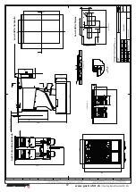
Installation of the heating basin (normal case)
Inlay and silicone seal
The heating basin is placed in the corresponding ope-
ning, the joint must be sealed with silicone. The holes
provided for frame assembly can be closed with blind
rivets or screws. The silicone joint must be checked re-
gularly for leaks in order to avoid the ingress of liquids
in the long term.
Installation of heating basin (additional parts)
With frame parts or upstand kitchen cover The
heating basin can also be attached to the table with
frame parts. The frame parts should be around 20mm
shorter than the outside dimensions of the pool. When
installing in a metal cover, this can also be folded up
analogously to the frame part. The frame parts are
not part of the Gastrofrit delivery. For the installation
of the frame parts, the opening must be 2mm larger.
The joint still has to be sealed with silicone. The frame
parts are bent from 1.5mm stainless sheet metal and
screwed to the table and basin.
Assembly instructions lift motor
Please make sure that you have connected the power
plug correctly if it was not installed by Gastrofrit AG.
The earth (color: yellow / green, symbol 0) and the
neutral wire (color blue, symbol N) are marked in the
connector housing, connect the phases so that the
brown wire is in the middle of the two black wires.
Electrical connection of the lifting motor
The connection cable contains the following 4
strands:
• yellow/green ground wire
• blue
neutral conductor
• brown
Phase lift motor up
• black
Phase lift motor down
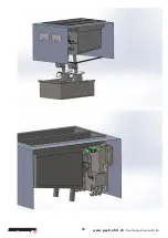
When you are standing in front of the device and have
tilted the cover towards you, you can connect the
strands as follows:
Please connect the earth to the metallic (gold-colored)
earth connection. The neutral conductor to the blue
clamp, the brown phase to the left gray clamp, the


