Gastops Ltd.
C009423, Rev. 4
page 46
All use of this publication and ChipCHECK by user shall be subject to the restrictions and conditions as set out in this publication.
•
Power down the ChipCHECK unit by pressing the Power Button on the front of the unit
(Refer to Figure 3-3).
•
Switch the Main Power Switch on the Power Entry Module to the off position (Refer to
Figure 3-3).
•
Disconnect the ChipCHECK unit’s power cord from the ChipCHECK unit.
•
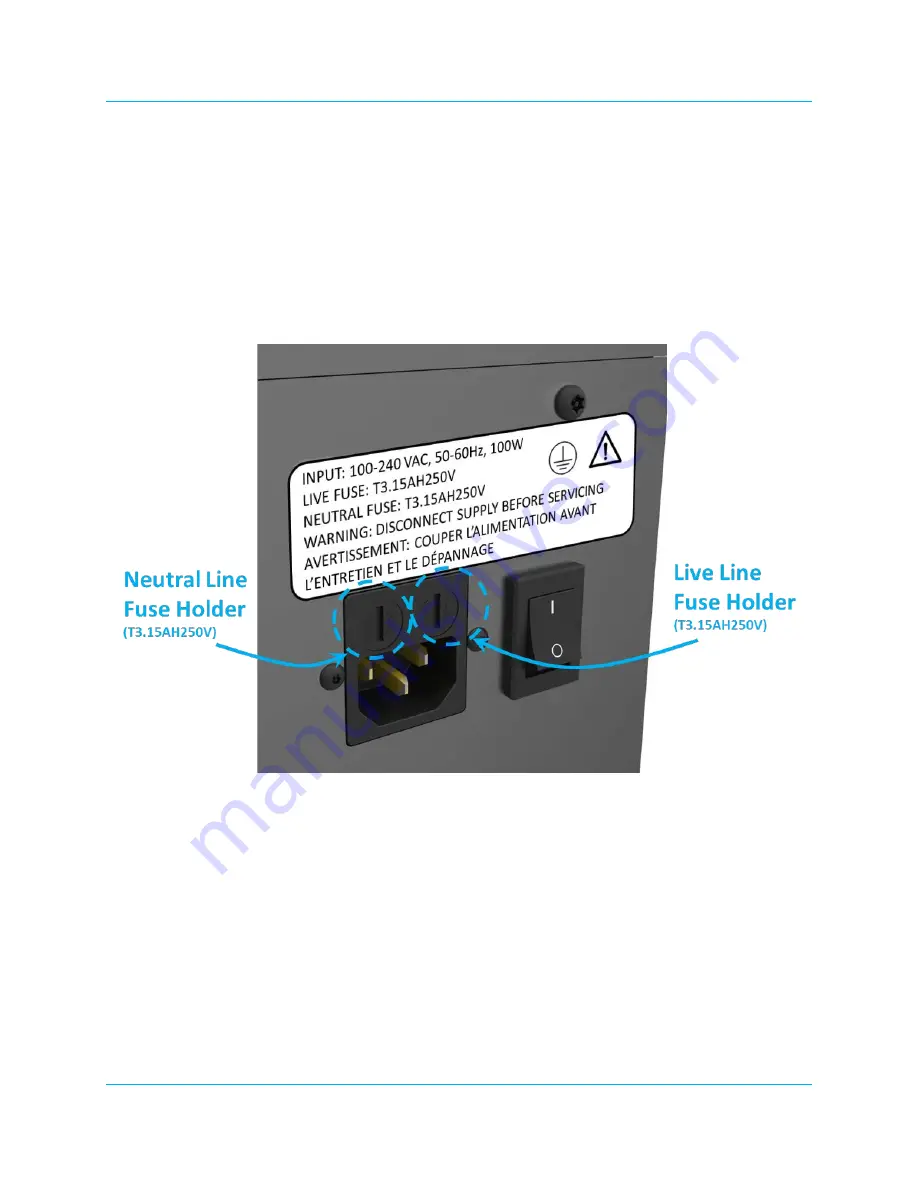
Remove the Fuse Holder and extract the Fuse (see Figure 6-3).
•
Insert the new Fuse and then reinsert the Fuse Holder into the Power Entry Module.
•
Follow the set up instructions as described in Section 3.3.
Figure 6-3: Power Entry Module and Main Power Switch
6.2 Unit Service (No Allowable Service)
In the event of any equipment failure or component replacement, Users are strictly forbidden to
perform any kind of service. There is absolutely NO SERVICE ALLOWED by the User.
Service activities are restricted to only Gastops authorized technicians who have the appropriate laser
safety training. There are no User serviceable parts. This unit is to be serviced or repaired only by
Gastops authorized technicians.
During servicing all precautions must be taken to avoid possible exposure to laser and collateral
radiation above Class 1. This is a Class 1 laser product that contains a Class 4 laser. Removal of any


