background image

www.desatech.com

113048-01F

12

Natural Gas

From Gas 

Meter (Blue

Flame - 4" W.C.

to 10.5" W.C. Pressure) 

(Plaque - 7" W.C. to 10.5" 

W.C. Pressure)

Propane/LP 

From External 

Regulator (11" W.C. to 14" 

W.C. Pressure)

INSTALLATION

Continued

Figure 14 - External Regulator With Vent 

Pointing Down

External Regulator

Propane/LP 
Supply Tank

Vent 
Pointing 
Down

Tee Joint
Reducer 
Bushing to 
1/8" NPT
1/8" NPT 
Plug Tap

Test Gauge Connection*

3/8" NPT 
Pipe Nipple

Heater 
Cabinet

Equipment 
Shutoff 
Valve *

3" 
Min.

Ground Joint 
Union

Tee Joint
Pipe 
Nipple
Cap

Sediment 

T

rap

Figure 15 - Gas Connection

Pressure 
Regulator

* A CSA design-certified equipment shutoff valve 

with 1/8" NPT tap is an acceptable alternative to 

test gauge connection. Purchase the optional CSA 

design-certified equipment shutoff valve from your 

dealer. See 

Accessories

, page 23.

  CAUTION:  Use  only  new, 

black  iron  or  steel  pipe.  Inter-

nally-tinned copper tubing may 

be used in certain areas. Check 

your  local  codes.  Use  pipe  of 

large enough diameter to allow 

proper gas volume to heater. If 

pipe is too small, undue loss of 

volume will occur.

Typical Inlet Pipe Diameters

20,000 Btu/hr or under - 3/8" or greater

25,000 Btu/hr or over - 1/2" or greater

Installation must include equipment shutoff valve, 

union and plugged 1/8" NPT tap. Locate NPT tap 

within reach for test gauge hook up. NPT tap must 

be upstream from heater (see Figure 15).

IMPORTANT:


Install an equipment shutoff valve 

in an accessible location. The equipment shutoff 

valve is for turning on or shutting off the gas to 

the appliance.
Apply  pipe  joint  sealant  lightly  to  male  NPT 

threads. This  will  prevent  excess  sealant  from 

going into pipe. Excess sealant in pipe could result 

in clogged heater valves.

  WARNING:  Use  pipe  joint 

sealant that is resistant to liquid 

petroleum (LP) gas. 

Install sediment trap in supply line as shown in 

Figure 15. Locate sediment trap where it is within 

reach for cleaning. Locate sediment trap where 

trapped matter is not likely to freeze. A sediment 

trap traps moisture and contaminants. This keeps 

them from going into heater controls. If sediment 

trap is not installed or is installed wrong, heater 

may not run properly.

IMPORTANT:


Hold the pressure regulator with 

wrench when connecting it to gas piping and/or 

fittings. Do not over tighten pipe connection to 

regulator. The regulator body could be damaged.

CHECKING GAS CONNECTIONS

 WARNING: Test all gas piping 

and  connections,  internal  and 

external to unit, for leaks after 

installing or servicing. Correct 

all leaks at once.

  WARNING:  Never  use  an 

open flame to check for a leak. 

Apply a noncorrosive leak detec-

tion fluid to all joints. Bubbles 

forming show a leak. Correct all 

leaks at once.

Summary of Contents for GMP16

Page 1: ...t use any phone in your building Immediately call your gas supplier from a neigh bor s phone Follow the gas supplier s instruc tions If you cannot reach your gas supplier call the re department Instal...

Page 2: ...g plate This appliance is not convert ible for use with other gases Aftermarket Completion of sale not for purpose of resale from the manufacturer State of Massachusetts The installation must be made...

Page 3: ...his heater WARNING Any change to this heater or its controls can be dangerous WARNING Donotuseablow er insert heat exchanger insert orotheraccessorynotapproved for use with this heater Due to high tem...

Page 4: ...and to replace any part of the control system and any gas control which has been under water 12 Turn off and let cool before servicing Only a quali ed service person should service and repair heater...

Page 5: ...e air that leaks around doors and windows may provide enough fresh air for combustion and ventilation However in buildings of unusually tight construction you must provide additional fresh air Unusual...

Page 6: ...used _______________ Btu Hr maximum the space can support _______________Btu Hr actual amount of Btu Hr used Example 51 200 Btu Hr maximum the space can support 60 000 Btu Hr actual amount of Btu Hr u...

Page 7: ...or use as supplemental heat Use this heater along with your primary heating system Do not install this heater as your pri mary heat source If you have a centralheatingsystem youmay run system s circul...

Page 8: ...y cause mildew to form from too much moisture See Air for Combustion and Ventilation page 5 If high hu midity is experienced a dehumidi er may be used to help lower the water vapor content in the air...

Page 9: ...re hold for the mounting bracket Marking Screw Locations 1 Tape mounting bracket to wall where heater will be located Make sure mounting bracket is level WARNING Maintain mini mumclearancesshowninFigu...

Page 10: ...e Wall anchors mounting screws and spacers are in hardware package The hardware package is provided with heater Attaching To Wall Stud Method For attaching mounting bracket to wall studs 1 Drill holes...

Page 11: ...er heater regulator damage could occur CAUTION For propane LP gas never connect heater di rectly to the propane LP supply This heater requires an external regulator not supplied Install theexternalreg...

Page 12: ...ve union and plugged 1 8 NPT tap Locate NPT tap within reach for test gauge hook up NPT tap must be upstream from heater see Figure 15 IMPORTANT Install an equipment shutoff valve in an accessible loc...

Page 13: ...pply piping system by either opening propane LP supply tank valve for propane LP gas or opening main gas valve located on or near gas meter for natural gas or using compressed air 3 Check all joints f...

Page 14: ...ol Models OPERATING HEATER FOR YOUR SAFETY READ BEFORE LIGHTING WARNING If you do not fol low these instructions exactly a re or explosion may result causing property damage per sonal injury or loss o...

Page 15: ...control used on these models differs from standard thermostats Standard thermostats simply turn on and off the burner The thermostat used on this heater senses the room temperature At times the room m...

Page 16: ...me BURNER FLAME PATTERN FOR BLUE FLAME HEATERS WARNING If yellow tipping occurs your heater could pro duce increased levels of carbon monoxide NOTICE Do not mistake orange ames with yellow tipping Dir...

Page 17: ...ions on the can you could damage the pilot assembly 1 Shut off the unit including the pilot Allow the unit to cool for at least thirty minutes 2 Inspect burner pilot for dust and dirt 3 Blow air acros...

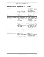
Page 18: ...ion 4 Air in gas lines when installed 5 Depleted gas supply pro pane LP gas only 6 ODS pilot is clogged 7 Gas regulator setting is not correct OBSERVED PROBLEM When ignitor button is pressed there is...

Page 19: ...gas company 1 Contact local natural or pro pane LP gas company 2 Clean burner see Cleaning and Maintenance page 17 or replace burner ori ce 1 Clean burner see Cleaning and Maintenance page 17 or repla...

Page 20: ...nto white powder residue 1 Plaque damaged 2 Inlet gas pressure is too low 3 Control knob set between locked positions REMEDY 1 Check burner for dirt and debris If found clean burner see Cleaning and M...

Page 21: ...t above 2 Control valve defective 1 Foreign matter between control valve and burner 2 Gas leak See Warning statement above 1 Not enough combustion ven tilation air OBSERVED PROBLEM Heater produces a c...

Page 22: ...mum 10 5 Minimum 4 Heater Weight 20 lb Shipping Weight 25 lb GMP26 AND GMP26T Propane LP Gas 26 000 Btu Hr GMP26 has variable settings Piezo Ignition Pressure Regulator Setting 8 W C Inlet Gas Pressur...

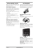
Page 23: ...t 1 866 672 6040 for referral information When calling DESA Heating Products have ready model number of your heater the replacement part number ACCESSORIES Purchase these heater accessories from your...

Page 24: ...www desatech com 113048 01F 24 ILLUSTRATED PARTS BREAKDOWN MODELS GMP16 GMP16T GMN18 GMN18T GMP26 GMP26T GMN30 AND GMN30T 14 15 8 5 6 7 4 3 1 2 16 10 9 11 12 13 17 See Pages 26 27...

Page 25: ...2 01 Control Rod Assembly 1 10 098325 01 Roll Pin 1 11 098354 03 Control Knob 1 12 099415 18 Gas Regulator Propane LP 1 099415 19 Gas Regulator Natural 1 13 104819 02 Regulator Bracket 1 14 098522 24...

Page 26: ...A 1 103353 04 Tubing Valve to Plaque A 1 11 103352 04 Tubing Valve to Plaque B 1 103353 05 Tubing Valve to Plaque B 1 12 103353 06 Tubing Valve to Plaque C 1 13 107660 01 Inlet Tube 1 107660 03 Inlet...

Page 27: ...ctor Plaque A or C 1 2 099056 25 Injector Plaque A or C 1 2 7 099056 01 Injector Plaque B 1 099056 02 Injector Plaque B 1 If replacing ODS pilot and your model is pre 2002 your part number will be 103...

Page 28: ...www desatech com 113048 01F 28 ILLUSTRATED PARTS BREAKDOWN MODELS GMP20BT GMN20BT GMP30BT AND GMN30BT 2 3 5 6 8 9 10 10 11 12 13 14 16 18 19 4 7 1 15 17 20...

Page 29: ...y 1 9 098271 09 Ignitor Cable 1 10 098249 01 Nut 2 11 110803 01 ODS Pilot Assembly NG 1 110803 02 ODS Pilot Assembly LP 1 12 103446 02 Burner 1 103447 06 Burner 1 13 099387 03 Pilot Tubing 1 14 103845...

Page 30: ...__ ______________________________________________________ ______________________________________________________ ______________________________________________________ ________________________________...

Page 31: ...__ ______________________________________________________ ______________________________________________________ ______________________________________________________ ________________________________...

Page 32: ...this product and or DESAHeating Products who will provide original factory replacement parts Failure to use original factory replacement parts voids this warranty The heater MUST be installed by a qu...

Reviews: