Installation, Operation & Maintenance Manual
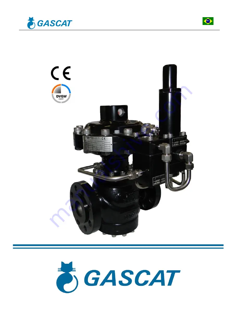
Pressure Regulating Valve
Model URANO FA/FF
Page 1: ...Installation Operation Maintenance Manual Pressure Regulating Valve Model URANO FA FF...
Page 2: ...PROCEDURE 16 3 7 ACTIVE MONITOR ASSEMBLY 17 4 0 INSTALLATION 19 4 1 FILTER 19 4 2 CLEANING 19 4 3 FLOW DIRECTION AND SYSTEM INTEGRITY 19 4 4 IMPULSE PICK UP 20 4 5 RECOMMENDED INSTALLATION SCHEME 22 4...
Page 3: ...these tasks Instruction manuals are provided for the operators guidance but it is assumed that they have a basic level of knowledge If there are any questions or ambiguities that affect the proper pro...
Page 4: ...ened the upstream pressure can pass through the regulator and over pressurize the downstream section of the main line All regulators etc shall operate with the regulation spring specified by the manuf...
Page 5: ...ficate carried out in the DVGW Deutscher Verein des Gas und Wasserfaches e V Technisch wissenschaftlicher Verein laboratory confirming its efficiency and compliance with DIN EN 334 Gas pressure regula...
Page 6: ...n the operation 2 3 4 COEFFICIENT OF FLOW Cv ND Cv KG 1 15 440 2 63 1950 3 123 3800 4 220 6850 6 486 15080 8 900 28250 NOTE 1 We suggest considering a 20 safety margin on the calculated value 2 When d...
Page 7: ...POINT PRESSURES Pressure regulators model URANO use two pilot models for pressure control called G 40 and G 42 The table below presents the adjustment ranges of each model PILOT G 40 SPRING COLOR PAR...
Page 8: ...up to 5 SSV AG up to 5 2 3 10 PRESSURE REGULATOR DIMENSIONS DIMENSIONS mm A RF B C ND 150 PN16 300 PN25 PN40 600 900 ANY CLASS ANY CLASS 1 184 197 476 412 2 254 267 268 516 412 3 298 318 337 381 620...
Page 9: ...main regulator diaphragm L If a decrease in downstream pressure occurs due to an increased consumption or a drop of the upstream pressure an imbalance between the spring I force on the pilot H diaphra...
Page 10: ...tallation and Operation Manual Urano Pressure Regulating Valve MI 31 Elaborado Verificado Aprovado CSQ Data Revis o P gina JJ JJ JM 05 07 21 05 10 de 74 FIGURE 1 URANO FAIL CLOSE A B D C E F G H L I K...
Page 11: ...under normal operating conditions since the main regulator spring is pressing the shutter for it to stay in the open position The pilot compares the output pressure sensed by the diaphragm H and contr...
Page 12: ...nstallation and Operation Manual Urano Pressure Regulating Valve MI 31 Elaborado Verificado Aprovado CSQ Data Revis o P gina JJ JJ JM 05 07 21 05 12 de 74 FIGURE 2 URANO FAIL OPEN A B D C L F K I G H...
Page 13: ...tion differences with different internal parts This differentiation is necessary for one to be able to operate FA pressure control valves and the other for use with FF regulators With pressure regulat...
Page 14: ...aphragm assembly A up or down causing the pilot shutter B to leave the seat C thus allowing the inlet pressure reduction and sending the gas at an appropriate pressure to load the main valve causing t...
Page 15: ...m and spheres collar monitoring the outlet pressure In case of outlet pressure increase or decrease the external bush will move up or move down allowing the spheres running out of channel and the main...
Page 16: ...hut off it is necessary to equalize the pressure before and after the shutter However it is necessary to use the integrated bypass in the reset lever See below how to proceed When there is a lock the...
Page 17: ...lure As already mentioned in this manual is important to bear in mind that the classification as FA or FF is given exclusively by the main valve diaphragm fail and lack of power for the shutter operat...
Page 18: ...Installation and Operation Manual Urano Pressure Regulating Valve MI 31 Elaborado Verificado Aprovado CSQ Data Revis o P gina JJ JJ JM 05 07 21 05 18 de 74 A C T I V E M O N I T O R A S S E M B L Y...
Page 19: ...uipment installation it is necessary to check if 1 The equipment is in perfect conditions or it has evidence of damage during transportation If so do not proceed with the installation and contact GASC...
Page 20: ...steel AISI 316 with OD to connect the regulator pick ups to the process To prevent dirt and condensates accumulation in impulse pick ups we recommend that their installation shall have a 5 to 10 slope...
Page 21: ...e pressure control valve therefore providing feed to the active valve booster When the URANO SC FF valve is mounted to operate in a system with only one pressure reduction stage this outlet is provide...
Page 22: ...INSTALLATION SCHEME 4 5 1 SINGLE REGULATOR 1 Inlet blocking valve 6 Partial relief valve 2 Cartridge type filter of 5 micra filtration degree 7 Outlet pressure gauge 2 way manifold 3 Inlet pressure g...
Page 23: ...than 5D if the installation project is analyzed and approved by GASCAT s engineering Another recommended installation option is to use a pneumatic lung to connect sensor pick ups taken near the equip...
Page 24: ...d by GASCAT s engineering 4 5 2 ACTIVE MONITOR SYSTEM 1 Inlet blocking valve 7 Pressure regulating valve URANO ACTIVE 2 Cartridge type filter of 5 micra filtration degree 8 Partial relief valve 3 Inle...
Page 25: ...for the sensor pick up may be less than 5D if the installation project is analyzed and approved by GASCAT s engineering Another recommended installation option is to use a pneumatic lung to connect se...
Page 26: ...rificado Aprovado CSQ Data Revis o P gina JJ JJ JM 05 07 21 05 26 de 74 3 Reduced damage to tubing during maintenance and transportation Note The position indicated for the sensor pick up may be less...
Page 27: ...FF REGULATOR 1 Inlet blocking valve 6 Pressure regulating valve URANO 2 Cartridge type filter of 5 micra filtration degree 7 Partial relief valve 3 Inlet pressure gauge 2 way manifold 8 Outlet pressu...
Page 28: ...e less than 5D if the installation project is analyzed and approved by GASCAT s engineering Another recommended installation option is to use a lung to connect sensor pick ups taken near the equipment...
Page 29: ...let output and bypass if applicable 3 Open vent valve downstream of the last pressure regulator installed on the span 4 Make sure that the station is depressurized 5 Check if all connectors are proper...
Page 30: ...relieved discharged Relieving the regulation spring we ensure that the valve will remain in the closed position when pressurized 3 Check if the discharge valve needle valve is open by 1 8 of a turn A...
Page 31: ...r this pressure rise and leave the pressure adjusted to a value at least 20 above the low set point pressure of the SSV 7 Once the SSV actuator is already pressurized you may release the by pass valve...
Page 32: ...ator of the reserve span assume regulation slowly press the regulation spring clockwise until the set point of the regulator reaches a value higher than the set point of the line in operation thus the...
Page 33: ...ve As the line shut off valves are closed we will use the vent valve to simulate a small flow and so proceed with the regulator adjustment before aligning the span 2 With the line still depressurized...
Page 34: ...ssure downstream of the regulator valve use a pressure gauge to monitor this pressure rise and leave the pressure adjusted to a value at least 20 above the low set point pressure of the SSV 7 Once the...
Page 35: ...t has been reached start to slowly unload release the pilot spring of the active valve by turning the adjustment screw counter clockwise This will reduce the setpoint of this regulator 15 Adjust the s...
Page 36: ...19 Once the pressure has stabilized open the vent valve by one half turn and check the adjustment accuracy 20 Once the pressure regulation agrees with the desired value you shall close the vent valve...
Page 37: ...tor regulator unloading outlet will be coupled to the outlet downstream of the active valve Thus the pilot of the monitor valve will remain open until it receives the corresponding pneumatic signal to...
Page 38: ...tion thus the reserve regulator will open slowly and assume the operation It is important that the two regulators remain with a set point difference of at least 5 10 so that there is no set point over...
Page 39: ...ferably by teams trained by GASCAT s instructors For training and qualification of operators and technicians please contact GASCAT through the e mails below to check on their availability E mail venda...
Page 40: ...4 Regulator FF Spring to close Replace the main diaphragm pos 4 Gas escape though the vent of the pilot cover Rupture of the diaphragm pos 19 Replace the diaphragm Gas escape though the booster gasket...
Page 41: ...parts as well as this instruction manual for reference of how to work safely and efficiently during the equipment maintenance ATTENTION GASCAT s pressure regulator valves components are developed man...
Page 42: ...31 Elaborado Verificado Aprovado CSQ Data Revis o P gina JJ JJ JM 05 07 21 05 42 de 74 6 1 RECOMMENDED REPAIR PARTS AND KITS 9 43 42 46 2 49 12 5 14 10 7 3 11 31 45 37 6 29 16 27 15 19 17 23 38 44 26...
Page 43: ...AGM 1 1 1 1 1 1 8 VIEWER 1 1 1 1 1 1 15 O RING 1 1 1 1 1 1 16 O RING 1 1 1 1 1 1 17 O RING 2 2 2 2 2 2 18 O RING 1 1 1 1 1 1 19 O RING 1 1 1 1 1 1 20 O RING 1 1 1 1 1 1 21 O RING 1 1 1 1 1 1 22 O RING...
Page 44: ...MI 31 Elaborado Verificado Aprovado CSQ Data Revis o P gina JJ JJ JM 05 07 21 05 44 de 74 11 47 46 57 2 36 53 15 6 7 18 12 9 4 13 35 49 41 51 8 16 33 20 31 19 22 23 24 21 27 25 26 28 29 42 48 30 32 5...
Page 45: ...4 6 8 2 DIAPHRAGM 1 1 1 1 1 1 10 VIEWER 1 1 1 1 1 1 19 O RING 1 1 1 1 1 1 20 O RING 1 1 1 1 1 1 21 O RING 3 3 3 3 3 3 22 O RING 1 1 1 1 1 1 23 O RING 1 1 1 1 1 1 24 O RING 1 1 1 1 1 1 25 O RING 1 1 1...
Page 46: ...Installation and Operation Manual Urano Pressure Regulating Valve MI 31 Elaborado Verificado Aprovado CSQ Data Revis o P gina JJ JJ JM 05 07 21 05 46 de 74...
Page 47: ...do CSQ Data Revis o P gina JJ JJ JM 05 07 21 05 47 de 74 BOOSTER G 43 PILOT G 42 40 BOOSTER G 43 POS DESCRIPTION QTY 8 GASKET 1 10 DIAPHRAGM 1 18 O RING 1 20 O RING 1 21 O RING 1 22 O RING 1 25 O RING...
Page 48: ...Installation and Operation Manual Urano Pressure Regulating Valve MI 31 Elaborado Verificado Aprovado CSQ Data Revis o P gina JJ JJ JM 05 07 21 05 48 de 74 BOOSTER G 43 PILOT G 42 40...
Page 49: ...Data Revis o P gina JJ JJ JM 05 07 21 05 49 de 74 BOOSTER G 44 PILOT G 42 40 BOOSTER G 44 POS DESCRIPTION QTY 9 GASKET 1 10 DIAPHRAGM 1 17 O RING 1 18 O RING 1 20 O RING 1 21 O RING 1 22 O RING 1 23 O...
Page 50: ...V POS DESCRIPTION QTY POS DESCRIPTION QTY 1 RELIEF 1 8 O RING 1 2 O RING 1 9 O RING 1 3 O RING 1 10 O RING 2 4 PARBAK RING 1 11a O RING 1 5 O RING 1 11b DIAPHRAGM 1 6 O RING 1 12 O RING 1 7 O RING 1 N...
Page 51: ...the components positions shown in the diagram of section 6 0 of this manual 3 Remove the pilot block and all connectors connected to the main valve 4 Proceed by removing the screws pos 5 5 Remove the...
Page 52: ...emove the diaphragm assembly Note Notice that the main valve diaphragm of the regulator model URANO is molded and the convex surface tends to remain with its face upwards in this assembly because the...
Page 53: ...rado Verificado Aprovado CSQ Data Revis o P gina JJ JJ JM 05 07 21 05 53 de 74 9 Release the screws pos 4 and remove the bottom cover of the actuator pos 31 10 Pull the actuator guide bushing pos 42 I...
Page 54: ...14 and release the shutter pos 38 Note The regulator model URANO of classes 150 300 and 600 are supplied with two shutters the one in use has the gasket facing the piston and the other is kept as a b...
Page 55: ...Installation and Operation Manual Urano Pressure Regulating Valve MI 31 Elaborado Verificado Aprovado CSQ Data Revis o P gina JJ JJ JM 05 07 21 05 55 de 74...
Page 56: ...all the conditions set out in item 4 6 1 of this manual have been observed 2 Under no circumstances start the equipment disassembly if it is pressurized The disassembly procedure given below refers t...
Page 57: ...ide sleeve pos 45 as illustrated below 7 3 Remove the diaphragm assembly Note Notice that the main valve diaphragm of the regulator model URANO is molded and the convex surface tends to remain with it...
Page 58: ...led in a line and for some reason cannot be removed from the same the procedure will be the same but with the lower cover facing down 12 Remove the screws of the intermediate pos 15 and release the in...
Page 59: ...threaded eyelets as given in the table below URANO ND PISTON THREAD 2 M8 x 1 25 3 M10 x 1 5 4 M14 x 2 0 6 M18 x 2 0 8 M22 x 2 25 Screw 2 bolts in the threaded holes and with the help of a combination...
Page 60: ...ssembly of the spring stop pos 50 by releasing the screws pos 7 18 Release the entire assembly and remove the opening spring pos 1 19 To remove the seat start by releasing the body bottom cover pos 49...
Page 61: ...proceeding with the equipment disassembly check if all the conditions set out in item 4 6 1 of this manual have been observed 2 Under no circumstances start the equipment disassembly if it is pressur...
Page 62: ...ta Revis o P gina JJ JJ JM 05 07 21 05 62 de 74 7 Turn the pilot block so that the bottom of the pilot faces up release the screws pos 16 15 and remove the bottom cover pos 47 49 8 Remove the spring a...
Page 63: ...JM 05 07 21 05 63 de 74 11 Remove the diaphragm plate and the lower diaphragm pos 9 11 turn the pilot block to the initial position and proceed by dismantling the bushing pos 35 32 12 Remove the diaph...
Page 64: ...below otherwise the seat will not match the shutter pos 29 26 2 After mounting the seat pos 46 48 in the movable base item 44 46 it is necessary to leave the seat perfectly aligned with the movable b...
Page 65: ...n 6 8 PROCEDURE FOR THE G 43 BOOSTER PRE REGULATOR DISASSEMBLY 1 Before proceeding with the equipment disassembly check if all the conditions set out in item 4 6 1 of this manual have been observed 2...
Page 66: ...Verificado Aprovado CSQ Data Revis o P gina JJ JJ JM 05 07 21 05 66 de 74 4 Remove the cover pos 39 and the diaphragm assembly pos 28 5 Lock the shaft pos 28 release the nut pos 11 remove the disc sp...
Page 67: ...MI 31 Elaborado Verificado Aprovado CSQ Data Revis o P gina JJ JJ JM 05 07 21 05 67 de 74 6 Now we will dismantle the bottom part of the booster To do this it is ideal to rotate the same so that the...
Page 68: ...Pressure Regulating Valve MI 31 Elaborado Verificado Aprovado CSQ Data Revis o P gina JJ JJ JM 05 07 21 05 68 de 74 7 Remove the filter element pos 26 and release the gasket pos 8 of the gasket holder...
Page 69: ...ome observations on specific points that must be examined closely during the booster reassembly 1 During assembly of the diaphragm assembly to the shaft pos 28 it is necessary to perform the plate spr...
Page 70: ...erved 2 Under no circumstances start the equipment disassembly if it is pressurized The disassembly procedure given below refers to the components positions shown in the diagram of section 6 0 of this...
Page 71: ...JJ JJ JM 05 07 21 05 71 de 74 5 Remove the booster shaft pos 34 6 Release the diaphragm item 10 by loosening the plate of the lower diaphragm pos 43 7 Now we will dismantle the bottom part of the boo...
Page 72: ...lating Valve MI 31 Elaborado Verificado Aprovado CSQ Data Revis o P gina JJ JJ JM 05 07 21 05 72 de 74 8 Release the gasket pos 9 of the gasket holder pos 47 and its respective O ring pos 22 9 Remove...
Page 73: ...ing valve due to the high differential pressure This internal relief is adjusted by the spring pos 4 compression during assembly of the diaphragm set onto the shaft pos 34 therefore during assembly it...
Page 74: ...ion Manual Urano Pressure Regulating Valve MI 31 Elaborado Verificado Aprovado CSQ Data Revis o P gina JJ JJ JM 05 07 21 05 74 de 74 TOOLS DIMENSIONS COMBINATION SPANNER 5 8 3 4 1 1 1 8 2 13mm ALLEN K...