GASBOY Series 9800Q
5-6
01/28/04
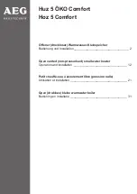
REPLACING THE LCD DISPLAY PCB
1.
Disconnect the cable [1] from the Sale Backlight PCB.
2.
Disconnect the ribbon cable [2] from the LCD Display PCB.
3.
Unsnap the LCD display PCB from standoffs [3].
4. Remove the two Phillips screws [4] and washers securing the Sale Backlight PCB to the
LCD Display PCB.
5.
Reverse Steps 1 through 4 to install the new LCD Display PCB.
6.
Verify that the jumper settings on the new LCD Display PCB match the jumper settings from
the defective LCD Display PCB. See the jumper settings in Section 3, Electronic Head
Assembly for verification.
Summary of Contents for SERIES 9800Q
Page 6: ......
Page 9: ...Chassis Wiring 01 28 04 2 3 115VAC 60 CYCLE PUMP WIRING ...
Page 10: ...GASBOY Series 9800Q 2 4 01 28 04 115VAC 60 CYCLE DISPENSER WIRING ...
Page 11: ...Chassis Wiring 01 28 04 2 5 230VAC 50 CYCLE PUMP WIRING ...
Page 12: ...GASBOY Series 9800Q 2 6 01 28 04 230VAC 50 CYCLE DISPENSER WIRING ...
Page 13: ...Chassis Wiring 01 28 04 2 7 115VAC 60 CYCLE FRONT LOAD OPTION PUMP WIRING ...
Page 14: ...GASBOY Series 9800Q 2 8 01 28 04 115VAC 60 CYCLE FRONT LOAD OPTION DISPENSER WIRING ...
Page 15: ...Chassis Wiring 01 28 04 2 9 230VAC 50 CYCLE FRONT LOAD OPTION PUMP WIRING ...
Page 16: ...GASBOY Series 9800Q 2 10 01 28 04 230VAC 50 CYCLE FRONT LOAD OPTION DISPENSER WIRING ...
Page 35: ...Electronic Head Assembly 01 28 04 3 19 Connectors Relay Drive Pump Motor Power ...
Page 56: ......
Page 60: ...GASBOY Series 9800Q 5 4 01 28 04 ...
Page 67: ...Replacement Instructions 01 28 04 5 11 ...
Page 70: ......