Garwoods EC-2978 Installation & Operating Instructions Manual Download Page 4


3


2

Installation Guideline


★ 

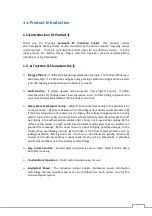
Installation should be followed below requirements


The  walls  on  top  of  the  working  face  and  next  to  the  installation  of  induction  cooker 
must be heat-proof. 


The laminated boards and adhesive used for installation must be heat-resistant. 


For  any  installation  method,  the  air  under  the  cooker  and  behind  the  cooking  range 
should  have  enough  space  for  cooling  in  order  to  ensure  the  safety  of  operating  the 
induction cooker. 


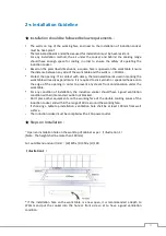
Based on the prescribed dimensions, a square hole is opened on the work table. Ensure 
the distance between any side of the work table and the walls is 

100mm. 


Protect the opening: If in contact with damp, the laminated boards used in marking the 
work table will easily expand more. It is required to stick varnish or special adhesive onto 
the  edge  of  the  opening  in  order  to  prevent  any  steam  from  condensation  under  the 
work table. 


For  any  condition  of  installation,  the  induction  cooker  should  have  a  good  ventilation 
condition with air inlet and air outlet not blocked. 


Don’t  place  other equipments on  the  working  face of  the  double  cooking  zones  of  the   
induction cooker and within the range of 30cm around the working face. 


If  choosing  a  table-top  installation,  ventilation  hole  shall  be  at  least  100mm  from  wall 
surface. 


The induction cooker must be complied with a 13A power outlet. 


★ 

Steps on Installation


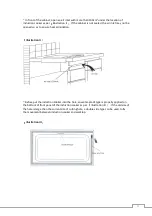
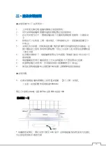
~ Open an installation hole on the worktop of cabinet as per 

illustration 1

(Note : The height shall be more than 100mm)   
 
Cut out dimensions(unit/mm)

(W) 670 x (D) 350 x (H) 100   


illustration 1


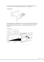
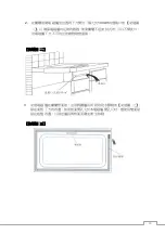
*  If  the  installation  hole  on  the  work  table  is  a  new  open,  it  is  recommended  a  depth  to 
370mm  and  put  the  cooker  into  the  hole  at  front  side  so  at  to  have  a  good  ventilation 
condition. 

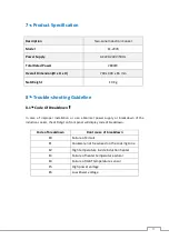
Summary of Contents for EC-2978

Page 1: ...0 Two Zone Induction Cooker Model EC 2978 Installation Operating Instructions...

Page 2: ...tructions 6 4 Operation Method 7 9 4 1 Operation Instructions 4 2 Usable and Non usable Cookware 4 3 Heating Power Distribution 4 4 Caution 5 Safety Precautions 9 10 5 1 Safety Notes 5 2 Warning 6 Dai...

Page 3: ...duct is on our top priority 1 Only cookware with a ferromagnetic material would be heated 2 If the body temperature of cookware is too high or the voltage change causes too strong electric current the...

Page 4: ...or special adhesive onto the edge of the opening in order to prevent any steam from condensation under the work table For any condition of installation the induction cooker should have a good ventila...

Page 5: ...o as to ensure heat elimination illustration II Before put the induction cooker into the hole an water proof type is properly applied on the bottom of front panel of the induction cooker as per illust...

Page 6: ...connection as per illustration IV illustration IV If the induction cooker is installed above an oven fix an insulation part at least 15cm under the induction cooker as per illustration V Also open an...

Page 7: ...one Control Panel 10 9 8 7 6 5 1 On Off Switch 3 Plus Key Timer 5 Minus Key Timer 7 Timer Key 9 Lock Key Panel Instruction 5 4 3 2 On Off Indicator 4 touchSlider bar Power 6 LED Digital Indicator 8 Ti...

Page 8: ...rease power level of another cooking zone so as to assure total power is under specified value Selecting Timer By pressing Timer key the time indicator will be on At the time by pressing Or key to set...

Page 9: ...e height 4mm Sorts of suitable cookware Stainless steel kettle iron tray bottom pan iron pot iron tray enamel pot etc Sorts of un suitable cookware Copper bronze and aluminum pot glass pot pottery pot...

Page 10: ...t in order to prevent any electric shock Do not put anything to block the air outlet Do not heat up unopened tins of food on the heating zone as pressure will build up in the tin and it can explode wh...

Page 11: ...y when it has cooled down Do not put any tinder of acid or alkaline materials near the induction cooker in order to avoid the electric circuits inside the stove from the erosive damages of acidity and...

Page 12: ...kdown In case of improper installation or use abnormal power supply or breakdown of the induction cooker the LED digit on front panel will display code of breakdown Code of breakdown Root cause of bre...

Page 13: ...to Usable and Non usable cookware0in the operation manual The heater works for a while and stops indicating E20 1 The inlet of fan is off 2 The fan stops working 3 The surrounding temperature is too...

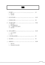
Page 14: ...13 14 I II 15 17 18 19 21 I II III IV 21 22 I II 22 23 23 24 I II...

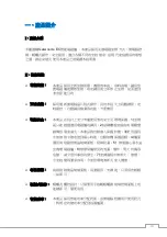
Page 15: ...14 I Garwoods EC II 1 2 3 4 5 6 7...

Page 16: ...15 1 2 3 4 100mm 5 6 7 30cm 8 100mm 9 13 1 100mm mm 670 x 350 x 100 370...

Page 17: ...16 2 100c 3...

Page 18: ...17 4 5 15cm 100c...

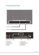
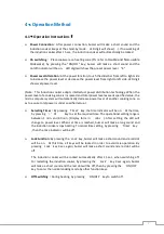
Page 19: ...1 2 1 2 10 9 8 7 6 5 34 54 6 7 84 6 7 94 4 5 4 3 4 4 4LED 4 3 4 18 2 1 A7...

Page 20: ...19 I LED 15 LED 4 LED BCDEFGHIJKLMNOPQRSTUVWXYIZ NO T _NO abc NOdefgThijklmnoYIZd NOTpqrNOsj abcNOtu LED 1 99 LED 3 15 3...

Page 21: ...20 II 1 12 26cm 20kg 4mm 4mm 120mm 2 3 III 7 7 vwx ywx z z 7 2800 0 0 6 2400 1 400 5 2000 2 800 4 1600 3 1200 3 1200 4 1600 2 800 5 2000 1 400 6 2400 0 0 7 2800...

Page 22: ...21 IV 3 20 LED E2 I...

Page 23: ...22 II...

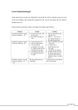
Page 24: ...23 EC 2978 AC220 240 50 2800 x x 700x 400x 65 10 I LED E0 E1 E2 E3 E4 IGBT E5 E6...

Page 25: ...24 II GHIs T I Ks K F d K GHI Y T s T GHI GHI GHI K a T Yg W a T GHI W l GHIs T...

Page 26: ...25 Sole Agent Araytron Technology Limited Enquiry 852 2397 3066 Fax 852 2397 3055 Website www garwoods com hk...

Reviews: