3
www.gantner.com
Valid as from November 27
th
2012 • Technical data subject to modifications without noitce!
DB_GAT-SMARTLOCK7001_EN_20.indd • PartNo: 426731
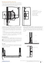
Mounting and installation instructions
The GAT Smart.Lock 7001 is fastened with 3 screws (1). Depending on
the type of locker, the lock can be mounted on the side wall of the locker
or in the intermediary wall of the locker. The door shackle is mounted with
the door and distance plate on the inside of the locker door.
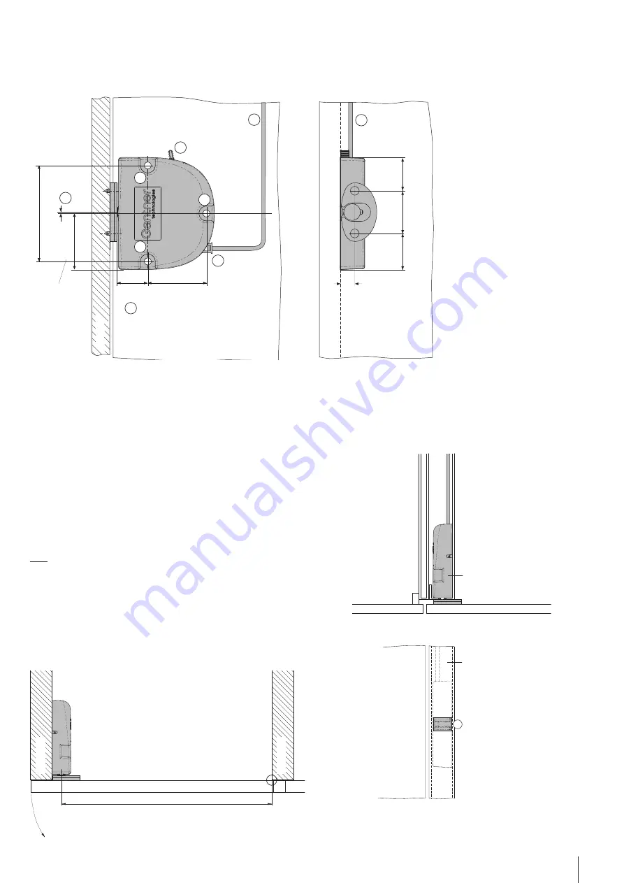
Installation dimensions for GAT Smart.Lock 7001 and door shackle
During the mounting, please pay particular attention to the following points:
- The distance between the GAT Smart.Lock 7001 and the distance plate
of the door shackle (2) must be between 1 and 1.5 mm when the door
is closed.
- The middle of the door shackle (3) must be 1 mm higher than the middle
of the door shackle opening in the GAT Smart.Lock 7001. This ensures
the door’s ability to close even if the door position is modified 3.5 mm
downwards or 1.5 mm upwards (tolerance ±2.5 mm).
Mounting safety pin
The GAT Smart.Lock 7001 is equipped with a mounting safety pin (6),
which prevents the unwanted locking of the locker. It must only be removed
after the mounting, electrical connection, and functional testing of the GAT
Smart.Lock 7001 have been completed. Therefore the mounting safety pin
is removed by pulling it straight out of the housing.
Door width
The minimum door width (measured from the door shackle to the hinge)
is 230 mm. If the door is narrower, the door shackle would hit the locker
when the door is being closed.
1. Fastening screws
2. Distance lock <-> distance plate
3. Offset door shackle <-> lock
4. Connection cable
5. Connection plug
6. Mounting safety pin
Installation of GAT Smart.Lock 7001 in the intermediate locker wall
If it is permitted by the type of locker, the GAT Smart.Lock 7001 can be
installed in the intermediate locker wall, as shown in the following figure.
This enables a hidden installation, showing only the opening for the door
shackle (7).
72.0 mm
42.0 mm
1.0 mm
1
1
1
2
3
6
5
4
4
11 mm
27 mm
25 mm
32 mm
44.0 mm
23.0 bis
23.5 mm
Middle of the door
shac
kle opening in the
GA
T Smart.L
oc
k 7
001
Loc
ker door
Locker door
Locker door
Centre of rotation of hinge
min. 230 mm
Loc
ker wall
Loc
ker wall
Locker door 2
Locker door 1
Locker 2
Locker 1
GAT Smart.Lock 7001
Intermediate loc
ker wall
Intermediate locker wall
7


