background image

Magnum 1000 Workgroup Hubs              Installation and User Guide (04/02)

35

www  GarrettCom  com

.

.

GarrettCom will carefully test and evaluate all returned products, will

repair products that are under warranty at no charge, and will return the warranty-
repaired units to the sender with shipping charges prepaid (see Warranty
Information, Appendix A, for complete details).  However, if the problem or
condition causing the return cannot be duplicated by GarrettCom, the unit will be
returned as:  

No Problem Found.


GarrettCom reserves the right to charge for the testing of non-defective

units under warranty.  Testing and repair of product that is not under warranty will
result in a customer (user) charge.

5.4

Shipping and Packaging Information

Should you need to ship the unit back to GarrettCom, please follow these

instructions:

1. 


Package the unit carefully.  It is recommended that you use the original
container if available.  Units should be wrapped in a "bubble-wrap" plastic
sheet or bag for shipping protection. ( You may retain all connectors and
this Installation Guide.)

CAUTION

Do not pack the unit in Styrofoam "popcorn" type packing

material.  This material may cause electro-static shock damage to the unit.

2.  Clearly mark the Return Material Authorization (RMA) number on the 
outside of the shipping container.
3.  GarrettCom is not responsible for your return shipping charges.
4.  Ship the package to:

GarrettCom, Inc.

47823 Westinghouse Drive

Fremont, CA  94539
Attn.:  Customer Service

APPENDIX A:  WARRANTY INFORMATION

GarrettCom, Inc. warrants its products to be free from defects in

materials and workmanship for a period of three (3) years from the date of
shipment by GarrettCom.

During this warranty period, GarrettCom will repair or, at its option,

replace components in the products that prove to be defective at no charge other
than shipping and handling, provided that the product is returned pre-paid to
GarrettCom.

This warranty will not be effective if, in the opinion of GarrettCom, the

product has been damaged by misuse, misapplication, or as a result of service or
modification other than by GarrettCom.

GarrettCom reserves the right to make a charge for handling and

inspecting any product returned for warranty repair which turns out not to be
faulty.

Please complete the warranty card as this acts as a product registration,

and mail it to GarrettCom within two weeks of your purchase.

Summary of Contents for Magnum 1008

Page 1: ...www GarrettCom com Magnum Workgroup Hubs Ten Series Models 1008 1016 and 1024 Installation and User Guide...

Page 2: ...agnum and Personal Switch are trademarks and Personal Hub is a registered trademark of GarrettCom Inc Important The Magnum 1000 series workgroup hub family contains no user serviceable parts Attempted...

Page 3: ...te frequency energy and if not installed and used properly that is in strict accordance with the manufacturer s instructions may cause interference to radio communication It has been tested and found...

Page 4: ...12 Special Option Second Bonus Port Models 1016 and 1024 18 2 5 Features and Benefits 19 2 6 Applications ERROR BOOKMARK NOT DEFINED 3 0 INSTALLATION 22 3 1 Table Top or Rack Mount 22 3 2 Powering the...

Page 5: ...Appendix B with 24VDC 125VDC option Rev C 04 01 Change the company name to GarrettCom Inc Formerly it was Garrett Communications There are no changes to the content of the material at this time Rev B...

Page 6: ...rts can be connected in strings Mixed Media Fiber Hub 16 port Stackable 10 100 auto sensing Dual Speed 8 port and 16 port Stackables 10 100 auto sensing Stackable Hubs SNMP Optional 10Mb series and 10...

Page 7: ...m 1 640 ft FOIRL multi mode Fiber optic 1 km 3 281 ft 10BASE FL multi mode Fiber optic 2 km 6 562 ft Single mode Fiber optic 10 km 32 810 ft Connectors TP RJ 45 shielded female AUI D sub 15 pin female...

Page 8: ...s yes Switch on Face Plate yes n a n a n a n a yes Fiber mm is multi mode cable normally used for 10BASE FL installations up to 2 0Km Fiber sgl m is single mode cable used for distant installations up...

Page 9: ...universal power supply up link switch on port 1 Stand alone or rack mount brackets ears included Magnum 1024 24 port 10BASE T Hub with shielded RJ 45 connectors and front mounted LEDs Includes a basic...

Page 10: ...ease complete and return the enclosed Product Registration Card to GarrettCom Inc as soon as possible In the event there are items missing or damaged contact the party from whom you purchased the prod...

Page 11: ...45 ports and one rear mounted AUI port The left most RJ 45 port port 1 is equipped with a slide switch to allow cascading or an up link without a crossover cable Refer to section 3 3 1 for details abo...

Page 12: ...est of the network Refer to Section 2 4 for Magnum Port Module information NOTE The Magnum 1008 s basic AUI port is NOT an RPM AUI it is simply an AUI port without any LEDs Figure 2 2 1c Rear view Mag...

Page 13: ...figured with any Magnum Port Module PM This option gives the Magnum 1016s and 1024s great flexibility to easily conform to any standard Ethernet media environment When configured with a Repeater Port...

Page 14: ...AUI port and Port Module Figure 2 3b shows the internal layout of the Magnum 1016 and 1024 Workgroup Hubs The Model 1024 is shown in the figure but all rear port connections are identical for the Mod...

Page 15: ...de local bridge isolation for the 1000 Workgroup Hub s users RPMs are available for the following six Ethernet connector types BNC ThinNet or 10BASE2 AUI 10BASE5 or ThickNet DB 15 female for most tran...

Page 16: ...Magnum Port Modules provide an optional electronic assembly and media connector for the Magnum 1000 Hubs bonus port slots and are not functional as stand alone units Figure 2 4c shows the physical di...

Page 17: ...y require a tee connector used as a tap to allow the 10BASE2 coax segment to continue on past the RPM BNC connection Magnum BPM BNC The RPM BNC module includes one partition PART and one receive RX LE...

Page 18: ...ncluding any cascading Refer to Section 3 3 2 for detailed information on the AUI port connector pins and cable length requirements 2 4 3 RPM DTE The Magnum RPM DTE is a module equipped with a 15 pin...

Page 19: ...NOTE The RPM FST circuit board contains a six pin jumper which controls the intensity of the transmitted signal By default the jumper is placed across pins 1 and 2 The jumper may be set as follows to...

Page 20: ...light red in color that is in the visible spectrum and which can be seen by looking into the port with the power on and with no cable connected The single mode TX port emits light outside of the visib...

Page 21: ...n be verified by noting that the port s LINK LED will illuminate when proper link is established The RPM TP will support 10BASE T unshielded twisted pair wiring UTP environments with maximum segment d...

Page 22: ...an FWD X LED which are visible from the exterior The FWD I LED blinks GREEN to indicate that packets are being forwarded INTO the local Magnum hub The FWD X LED blinks GREEN to indicate that packets a...

Page 23: ...The Magnum BPM TP card is equipped with a single RJ 45 connector and supports standard length Ethernet twisted pair segments The RJ 45 connector is shielded to minimize emissions and allows both unshi...

Page 24: ...connected into header J1 RPM In order to install a second PM it is necessary to replace the factory installed Basic AUI Port connected into header J1 with the desired Port Module This procedure requir...

Page 25: ...lows local bridge isolation of the Magnum 1000 segment from the connected network Inter operable with other Ethernet Devices Magnum 1000 Workgroup Hubs are completely inter operable with any Ethernet...

Page 26: ...rnet media Figure 2 5b shows two workgroups connected to a ThinNet 10BASE2 segment One of the workgroups is comprised of two Magnum 1000 s cascaded by means of the up link switch of a port 1 for detai...

Page 27: ...he network traffic is kept local i e is contained inside of each Magnum 1000 Hub segment by the BPMs and does not consume bandwidth on the rest of the network Refer to section 4 2 Magnum 1000 BPM Loca...

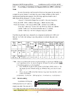
Page 28: ...iversal power supply and have a recessed male IEC connector for the AC power cord at the right rear A six foot 115 VAC 60 Hz power cord is supplied with each unit shipped within the United states and...

Page 29: ...BPM AUI Drop Cable 10BASE5 DTE male RPM DTE Twisted Pair 10BASE T RJ 45 RPM TP BPM TP Fiber mm1 FOIRL ST RPM FST RPM SMF BPM FST Fiber mm1 10BASE FL ST or SC RPM FST RPM SMF BPM FST Fiber sgl m2 ST R...

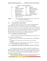
Page 30: ...d 2 Engage the AUI connector slide lock to insure maximum connectivity 3 Connect the opposite end of the cable into a network AUI port This could be a network backbone transceiver a hub or fan out wit...

Page 31: ...o use a tee connector when the BNC cable is ending at the connection to this PM Some applications may require a tee connector used as a tap to allow the 10BASE2 coax segment to continue on past the PM...

Page 32: ...type applies to FOIRL and 10BASE FL applications using an RPM SMA card used with SMA type fiber connectors Follow the five steps as described in the Section 3 3 5 above When connecting fiber media to...

Page 33: ...ide guidance to network designers and installers Fiber Port Module Speed Std Mode Std km fdx hdx Wave length nm Cable Size m X mitr Output PT dB R cvr Sens PR dB Worst OPB dB Worst distance Km fdx typ...

Page 34: ...re popular in TELCO Industry and consider as a standard for Rack mounting purpose The 23 brackets are mainly being used for Huge rack mounting frame to provide more secure and stability to the unit in...

Page 35: ...um output packet to the other port is 96 bits long Preamble Regeneration Magnum 1000 Hubs will add bits to the preamble so that the output packet contains a minimum of a 64 bit preamble Status LEDs Ea...

Page 36: ...on the attached segment If the packet s source is internal it is forwarded to the outside only if the destination address is not in the address table Figure 4 2a shows an internal packet being forwar...

Page 37: ...BPMs is shown in Table 4 2 Table 4 2 BPM Functionality Packet Source Destination Address Table Filter Forward Source Address Address Maintenance Action Internal Not in table Not in table Add source to...

Page 38: ...D X status LEDs The FWD I LED flashes when packets are forwarded into the local segment The FWD X LED flashes when packets are forwarded out of the local segment 5 Self test Diagnostics A Magnum BPM r...

Page 39: ...ation Section of the applicable chapter of this manual Also check to make sure that the various components of the network are interoperable 2 Check the cables and connectors to ensure that they have b...

Page 40: ...kstations terminals and printers plus the various network media types being used 4 A record of changes that have been made to your network configuration prior to the occurrence of the problem Any chan...

Page 41: ...Styrofoam popcorn type packing material This material may cause electro static shock damage to the unit 2 Clearly mark the Return Material Authorization RMA number on the outside of the shipping cont...

Page 42: ...x P S rating With the exception of the power supply all specifications and functions of Magnum 1000 Workgroup Hubs 48VDC 24VDC 125VDC models are identical to those listed in the main manual B2 0 48VDC...

Page 43: ...event of a power failure The 24VDC 125VDC solution are particularly useful in the Industrial environment where it is common facilities to operate on 24VDC 125VDC power The 125VDC solution is mainly u...

Page 44: ...ments 1 Minimum 14 AWG cable for connection to a Centralized DC power source 2 Fastening torque of the lugs on the terminal block 9 inch pound max 3 Centralized DC Power Source cable securement use at...

Reviews: