VHF 100/00 Series Radio Installation Instructions
Step 3: Connect the VHF 100/200 Series Radio to Power
The VHF 100/200 series radios have a power-cable wiring harness that connects to power and provides interface capabilities for connecting
external devices.
Notes:
The replacement fuse on the power cable wiring harness is a 10 A, slow-blow fuse.
If it is necessary to extend the power wires, use 18 AWG wire.
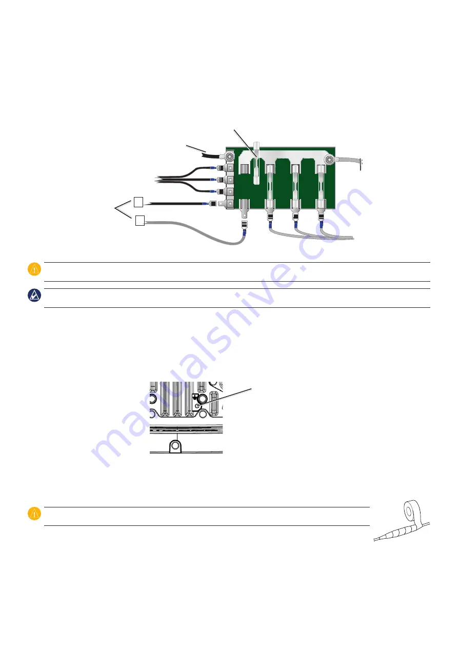
If your boat has an electrical system, you might be able to wire the radio directly to an unused holder on your current fuse block. If you
are using the fuse block, remove the in-line fuse holder supplied with the radio. You can also wire the radio directly to the battery.
-
+
To 10.8-15.6 Vdc
boat supply
10 A fuse
Boat ground
+
-
To VHF 100 or
00 series radio
Fuse Block
CAUtIoN:
The VHF 100/200 series radio maximum input voltage is 15.6 Vdc. Do not exceed this voltage, because this can damage the radio and
void the warranty.
Note:
During a typical installation, use only the red and black wires. The other wires are used for NMEA 0183 and other connections, and do not
have to be connected for normal operation of the radio. For information on connecting to a NMEA 0183-compatible device, see
To install the power-cable wiring harness:
1. Use a test light or voltmeter to determine the polarity of the voltage source.
2. Connect the red (+) wire on the power-cable wiring harness to the positive voltage terminal on the battery. (If you use the fuse block on
the boat, route the positive connection through the fuse, as shown on the Fuse Block diagram.)
3. Connect a ground wire (not included) from the ground connector screw to the negative voltage terminal on the battery, using 18 AWG
wire.
Ground connector
screw
4. Connect the black (-) wire on the power-cable wiring harness to the negative voltage terminal on the battery.
5. Install or check the 10 A fuse (on the fuse block or in the in-line holder).
6. Connect the power-cable wiring harness red and black wires to the red and black wires on the back of the radio (connect the two red
wires together and the two black wires together).
CAUtIoN:
Cover the connections with a waterproof, adhesive tape, such as rubber vulcanizing tape, to prevent water from
seeping into the radio.
•
•
•


