


Trolling Motor Shaft Orientation
The angle of installation depends on the side of the trolling motor shaft you mount the bracket on, and your
desired field of view.
TIP: No tools are necessary to change the orientation from forward to down. Turn the mount one click to
change the orientation from forward to down.
Port side, forward view
Port side, downward view
Starboard side, forward view
Starboard side, downward view
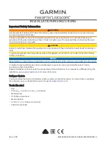
Installing the Transducer on a Transom
Optional Spray Shield Accessory
If necessary, to reduce spray from the transducer, you can install an optional spray shield (010-12406-00). Go
to
or contact your Garmin dealer for information.
Assembling the Transom-Mount Hardware
1 Attach the transducer mount bracket to the transducer using the mounting screws and lock
washers
.
2 Attach the transducer mount bracket to the transom mount bracket using the bolts , flat washers ,
and lock nuts .
NOTE: The recommended torque applied to the bolts is 15 lb-ft. (20 N-m).
7