background image

Mode S Data Transmission

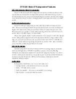
In addition to 4096 code and pressure altitude, the GTX 330 is capable of transmitting 

aircraft identification, transponder capability, and maximum speed range.  Aircraft 
identification is commonly referred to as 

FLT ID

 (Flight Identification).  The GTX 330 may be 

configured by the installer to allow the flight crew to enter 

FLT ID

 for each flight.  An example 

is when air-carrier service requires changing the 

FLT ID

.

The 

FLT ID

 may consist of the aircraft registration or a flight number as agreed upon with 

the local aviation authority.  In either case, the 

FLT ID

 must be the same aircraft identification 

that appears in the flight plan to correlate the aircraft identification seen on ATC radar with the 
correct voice call sign for the aircraft.  If no flight plan is filed with the aviation authority (as 
may be permitted by regulations), the 

FLT ID

 entered is the aircraft registration marking.

When flight crew entry of the 

FLT ID

 is not required, the installer configures the 

system to report the aircraft identification according to local aviation requirements.  In this 
configuration, alteration of the 

FLT ID

 by the flight crew is not possible.

Altitude Monitor Operation

To operate the Altitude Monitor:

1)

  Climb to assigned altitude.

2)

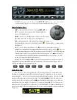
  Press the 

FUNC 

key until ALT MONITOR is displayed.

3)

  Press 

START/STOP 

key to start monitoring altitude.

4)

  Press 

START/STOP

 key again to cancel Altitude Monitor.

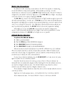
Altitude deviation is shown in hundreds of feet ABOVE or BELOW the selected altitude.  

When the aircraft’s altitude exceeds the deviation limit, ABOVE or BELOW flashes and an 
audio tone or the message “Leaving Altitude” is heard.  ABOVE or BELOW flashes until the 
aircraft returns to within 100’ of the selected altitude.

To select a new monitored altitude, press the 

START/STOP

 key to deactivate, then press 

again to activate the new monitored altitude.

If another function is selected for viewing, such as a Timer or Pressure Altitude, the 

Altitude Monitor is automatically displayed with a flashing alert when the altitude excursion 
exceeds the configured deviation value.  The Altitude Monitor stops when the current 
deviation exceeds 1000 feet plus the configured deviation value.

The maximum configured deviation values that can be set by a Garmin authorized service 

center are as follows:

Flight Level or Feet Maximum Limits – 300 feet BELOW, 0 feet to 1999 feet ABOVE
Meters Maximum Limits – 300 meters BELOW, 0 meters to 609 meters ABOVE

Summary of Contents for GTX 330 / 330ES

Page 1: ...Mode S Transponder Pilot s Guide GTX 330 330D ...

Page 2: ...ICENSE AGREEMENT PLEASE READ THIS AGREEMENT CAREFULLY Garmin grants you a limited license to use the software embedded in this device the Software in binary executable form in the normal operation of the product Title ownership rights and intellectual property rights in and to the Software remain in Garmin You acknowledge that the Software is the property of Garmin and is protected under the Unite...

Page 3: ...me states do not allow the exclusion of incidental or consequential damages so the above limitations may not apply to you Garmin retains the exclusive right to repair or replace the unit or software or offer a full refund of the purchase price at its sole discretion SUCH REMEDY SHALL BE YOUR SOLE AND EXCLUSIVE REMEDY FOR ANY BREACH OF WARRANTY To obtain warranty service contact your local Garmin A...

Page 4: ...mode may be selected in aircraft not equipped with an optional altitude encoder however the reply signal will not include altitude information Any time the function ON or ALT is selected the transponder becomes an active part of the Air Traffic Control Radar Beacon System ATCRBS The transponder also responds to interrogations from TCAS equipped aircraft Code Selection Code selection is done with e...

Page 5: ...s Pressure Altitude Flight Time Altitude Monitor Count Up and Count Down timers Also displays Outside Air Temperature Density Altitude Contrast Display and ADS B Operation dependent upon installation configuration START STOP Starts and stops the Altitude Monitor Count Up Count Down and Flight timers CRSR Initiates starting time entry for the Count Down timer and cancels transponder code entry CLR ...

Page 6: ...Controlled by START STOP CLR and CRSR keys The initial Count Down time is entered with the 0 9 keys CONTRAST This page is only displayed if manual contrast mode is selected during installation configuration Contrast is controlled by the 8 and 9 keys DISPLAY This page is only displayed if manual backlighting mode is selected during installation configuration Backlighting is controlled by the 8 and ...

Page 7: ...he Count Down timer 1 Press the FUNC key until COUNT DOWN is displayed 2 Press CRSR and use the 0 9 keys to set the initial time All digits must be entered use the 0 key to enter leading zeros 3 Press START STOP to begin count down 4 Press START STOP again to pause the timer 5 When the Count Down timer expires the COUNT DOWN banner is replaced with a flashing EXPIRED the message Timer Expired is h...

Page 8: ...he FLT ID by the flight crew is not possible Altitude Monitor Operation To operate the Altitude Monitor 1 Climb to assigned altitude 2 Press the FUNC key until ALT MONITOR is displayed 3 Press START STOP key to start monitoring altitude 4 Press START STOP key again to cancel Altitude Monitor Altitude deviation is shown in hundreds of feet ABOVE or BELOW the selected altitude When the aircraft s al...

Page 9: ... FLT ID field If the Flight ID appearing at turn on is correct press the CRSR key to move the cursor to the OK field Press CRSR again to accept the FLT ID The transponder then begins normal operation When no FLT ID appears or the FLT ID must be changed press the number keys corresponding to the alphanumeric character entry For example to enter the letter R press the 5 key four times Each time an a...

Page 10: ...tion in the cockpit for non TCAS equipped aircraft Transponder equipped aircraft can be displayed within the coverage volume within range of your position on indicators such as a Garmin GNS 430 or GNS 530 GNS 480 and GMX 200 Aircraft without an operating transponder are invisible to TIS Refer to 400 500 series GNS 480 or GMX 200 pilot literature for details GTX 330 ES Options Automatic Dependent S...

Page 11: ......

Page 12: ...l Inc 1200 East 151st Street Olathe Kansas 66062 U S A Garmin Europe Ltd Liberty House Bulls Copse Road Hounsdown Business Park Southampton SO40 9RB U K Garmin Corporation No 68 Jangshu 2nd Road Shijr Taipei County Taiwan www garmin com Part Number 190 00207 00 Rev F ...

Reviews: