190-01007-C1
GTN Xi Part 23 AML STC Maintenance Manual
Rev. 1
Page 7-17
7.3.4 Transponder
1. For remote transponders, configure transponder per Section 7.3.4.1.
2. Perform interface check per Section 7.3.4.2.
7.3.4.1 Remote Transponder Configuration
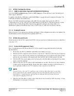
A remote transponder can be configured by the GTN Xi through RS-232 if a transponder is configured for
one of the RS-232 ports. To configure the transponder, it must first be selected as
Present
and the type of
transponder installed must be specified. To do this, access the
Interfaced Equipment
page on the
GTN Setup
page. Next, go to the
External Systems
page and touch the
XPDR
key. This displays the
XPDR( )
page, which allows the remote transponder to be configured. The remote transponder should be
configured in accordance with the installation manual for that specific transponder.
NOTE
If the GTN Xi controls any transponder (GTX 3XX/3XXR), then that transponder will boot
into the same mode (Normal or Configuration) as the GTN Xi.
NOTE
If the GTN Xi is not communicating with the GTX transponder, all of the editable fields for
the setup items shown in the following sections will be dashed out. If the fields are dashed
out, check the wiring and pin connections from the GTN Xi to the transponder.
NOTE
The GTX 335R/345R must be configured through the GTX 3X5 Install Tool. Refer to
GTX 3X5 TSO Installation Manual for more information.
NOTE
The GTN Xi can interface to the GTX 3XX; however, configuration of the panel-mounted
GTX 3XX is not supported. These transponders should be configured per their installation
manuals rather than through the GTN Xi.
7.3.4.2 Transponder Interface Check
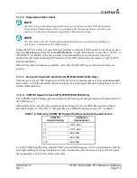
If the GTN Xi is interfaced to a GTX 32/33/3X5R remote transponder, or a GTX 3XX configured as a
remote transponder, the following checks must be completed:
1. With the GTN Xi in Normal mode, and the transponder powered on, go to the home page and
ensure there is not a red “X” over the transponder data field on the screen.
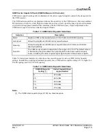
2. Check that a code can be entered into the Code field. Enter a code using the keypad and then touch
the
Enter
key. Check that the code that was entered is displayed in the Transponder Data field.
3. If dual transponders are installed, select
Transponder 2
and perform steps 1 and 2 for the second
transponder as well.
4. To verify wiring is not crossed, open the Transponder 1 circuit breaker and verify the
Transponder 1 data field has a red “X”.
5. Repeat the steps 1 through 3 for GTN Xi #2.

