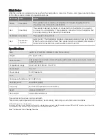
Garmin GSD 26 Installation Instructions Manual Download Page 13

Blink Codes

After the sounder is installed, it turns on when the chartplotter is turned on. The two-color (green and red) status 
LED on the sounder indicates its operational status.

LED Color State

Status

Green

Slow blink

The sounder is connected to a chartplotter and is operating properly. You 
should see sonar data on the chartplotter.

Red

Slow blink

The sounder is turned on, but is not connected to a chartplotter, or is waiting 
to connect to a chartplotter. If the sounder is connected to the chartplotter and 
this code persists, check the wiring connections.

Red/Green Slow blink

The sounder is in test mode.

Red

Rapid blink 
sequence

System error. The chartplotter displays a message indicating the type of failure. 
When the error condition is fixed, the sounder must be completely disconnected 
from and reconnected to its power source to clear the error.

Specifications

Size

L x W x H: 274 x 373 x 100 mm (10.8 x 14.7 x 3.9 in.)

Weight

5.16 kg (11.37 lb.)

Case material

Fully gasketed, aluminum and steel housing with plastic access panel, water resistant 
to IEC 60529 IPX7.

Temperature range

From 5 to 158°F (from -15 to 70°C)

Power input

10–35 V

Power usage

100 W maximum

Fuse

10 A

Compass safe distance 60 cm (23.6 in.)

Sounder power

25-3,000 W (RMS)*

Frequency

25-210 kHz (dependent on transducer)

Depth

3,048 m (10,000 ft.)**

Data output

Garmin Marine Network

*Dependent on transducer rating and depth
**Maximum depth dependent on transducer, water salinity, bottom type, and other water conditions.

© 2014–2022 Garmin Ltd. or its subsidiaries
Garmin

®

 and the Garmin logo are trademarks of Garmin Ltd. or its subsidiaries, registered in the USA and other countries. GSD and GMS

 are trademarks of Garmin Ltd. 

or its subsidiaries. These trademarks may not be used without the express permission of Garmin.
Airmar

 is a trademark of Airmar Technology Corporation.

GSD 26 Installation Instructions

13

Summary of Contents for GSD 26

Page 1: ...ection and a dust mask when drilling cutting or sanding NOTICE When drilling or cutting always check what is on the opposite side of the surface This equipment must be installed by a qualified marine...

Page 2: ...berglass with screws it is recommended to use a countersink bit to drill a clearance counterbore through only the top gel coat layer This will help to avoid any cracking in the gel coat layer when the...

Page 3: ...gn the notch on the end of the power cable with the power port on the device and press the cable into place 6 Tighten the locking ring 7 Repeat steps 4 and 5 for the network cable and connect the devi...

Page 4: ...Transducer Wire Color Tables page 11 for specific examples of Garmin wire colors 1 Connect the uninsulated section of each wire to the terminal block using a 3 mm flat screwdriver 2 Connect the bare s...

Page 5: ...is ground post to the boat water ground circuit NOTE The boat battery ground is an acceptable alternative if your vessel does not have a designated water ground circuit 2 Mount the sounder Mounting th...

Page 6: ...e high frequency terminal block damages the device and the transducer You can use these diagrams to identify the connection points for your transducer wires on the GSD 26 terminal block Locate your CH...

Page 7: ...Single Element CHIRP Spread Spectrum GSD 26 Installation Instructions 7...

Page 8: ...Dual Element CHIRP Spread Spectrum with Temperature and XID NOTE The temperature and XID wires can be connected at either location 8 GSD 26 Installation Instructions...

Page 9: ...Dual Element CHIRP Spread Spectrum with XID NOTE The XID wires can be connected at either location GSD 26 Installation Instructions 9...

Page 10: ...Dual Element CHIRP Spread Spectrum with Separate Temperature Sensor NOTE The temperature and XID wires can be connected at either location 10 GSD 26 Installation Instructions...

Page 11: ...Separate Speed Sensor NOTE The XID wires can be connected at either location Transducer Wire Color Tables You can use these tables to help identify wire functions on certain Garmin or Airmar transduc...

Page 12: ...1 Bare Black White Brown NA White Orange Blue Bare Black Bare Airmar B175H NA NA NA Brown NA White Orange Blue Bare Black Bare Airmar B175L Blue White Bare Black White Brown NA White Orange NA NA NA B...

Page 13: ...ce to clear the error Specifications Size L x W x H 274 x 373 x 100 mm 10 8 x 14 7 x 3 9 in Weight 5 16 kg 11 37 lb Case material Fully gasketed aluminum and steel housing with plastic access panel wa...

Page 14: ...2014 2022 Garmin Ltd or its subsidiaries support garmin com...

Reviews: