4
GSD 21 Sonar Module
I
NSTALLATION
I
NSTRUCTIONS
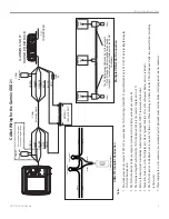
W
IR
E
C
O
LO
R
GARMIN GSD 21
SOUNDER MODULE
BL
AC
K
O
R
AN
G
E
R
ED
W
H
IT
E/
BL
U
E
BL
AC
K
R
ED
W
H
IT
E/
BL
U
E
W
H
IT
E/
BR
O
W
N
W
H
IT
E/
BR
O
W
N
W
IR
E
C
O
LO
R
2
A
FU
SE
O
R
AN
G
E
2
A
FU
SE
TO
TRANSDUCER
BA
TT
ER
Y
10
-3
5
VO
LT
S
D
C
Serial W
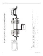
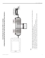
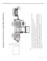
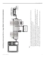
iring for the Garmin GSD 21 to a Single GPSMAP
3005C/3205
Notes:
1.
You can extend the serial/power wiring of the GSD 21 power/data cable up to 100 ft (30 m) total length. Use the CANet Extension Cable or 22
AWG, 4-conductor shielded cable for data connections and 18
AWG for power
.
2.
Ground the drain wire at the display unit. Do not ground the drain wire on the sonar unit.
3.
Refer to the chartplotter
’s specifi
c Installation Instructions for wiring the GPS 17 sensor and other devices.
4.
When crimping the 3-wire connector
, use a standard pair of pliers and make sure the button is fully depressed into the connector
.
Summary of Contents for GSD 21 - GPS Receiver Remote Sonar Sensor
Page 1: ...GSD 21 Sounder Module installation instructions...
Page 13: ......


