


• Included power cable and an ANT wireless connection
(
Pairing the GRID 20 Device with the Chartplotter
• AA batteries (not included) and an ANT wireless connection
(
Pairing the GRID 20 Device with the Chartplotter
NOTE:
The NMEA 2000 connection method can be used to
remove all risk of issues caused by wireless interference from
other devices and in cases where there are wireless range
concerns. The cables necessary to connect to the NMEA 2000
network are not included.
After you supply power to the GRID 20 device, you must pair it
with the chartplotter to make the data connection (
GRID 20 Device with the Chartplotter
).
NMEA 2000 Connection Considerations
NOTICE
If you are connecting to an
existing
NMEA 2000 network,
identify the NMEA 2000 power cable. Only one NMEA 2000
power cable is required for the NMEA 2000 network to operate
properly.
A NMEA 2000 Power Isolator (010-11580-00) should be used in
installations where the existing NMEA 2000 network
manufacturer is unknown.
You can connect the GRID 20 device to a NMEA 2000 network
on your boat to provide a power and data connection. If you
connect the GRID 20 device to a NMEA 2000 network, you do
not need to use batteries, the included power cable, or an ANT
wireless connection.
If you need to create a NMEA 2000 network and are unfamiliar
with it, go to
for more information.
Compatible Garmin chartplotter
GRID 20
Ignition or in-line switch
NMEA 2000 power cable
NMEA 2000 drop cable
12 Vdc power source
NMEA 2000 terminator or backbone cable
NMEA 2000 T-connector
NMEA 2000 terminator or backbone cable
After making the NMEA 2000 network connection, you must pair
the GRID 20 device with the chartplotter (
).
Connecting to Power
WARNING
When connecting the power cable, do not remove the in-line
fuse holder. To prevent the possibility of injury or product
damage caused by fire or overheating, the appropriate fuse
must be in place as indicated in the product specifications. In
addition, connecting the power cable without the appropriate
fuse in place voids the product warranty.
1
Route the power cable to the power source and to the device.
2
Connect the red wire to the positive (+) battery terminal, and
connect the black wire to the negative (-) battery terminal.
3
Connect the power cable to the device, and turn the locking
ring clockwise to tighten it.
After connecting to power, you must pair the device with the
chartplotter (
Pairing the GRID 20 Device with the Chartplotter
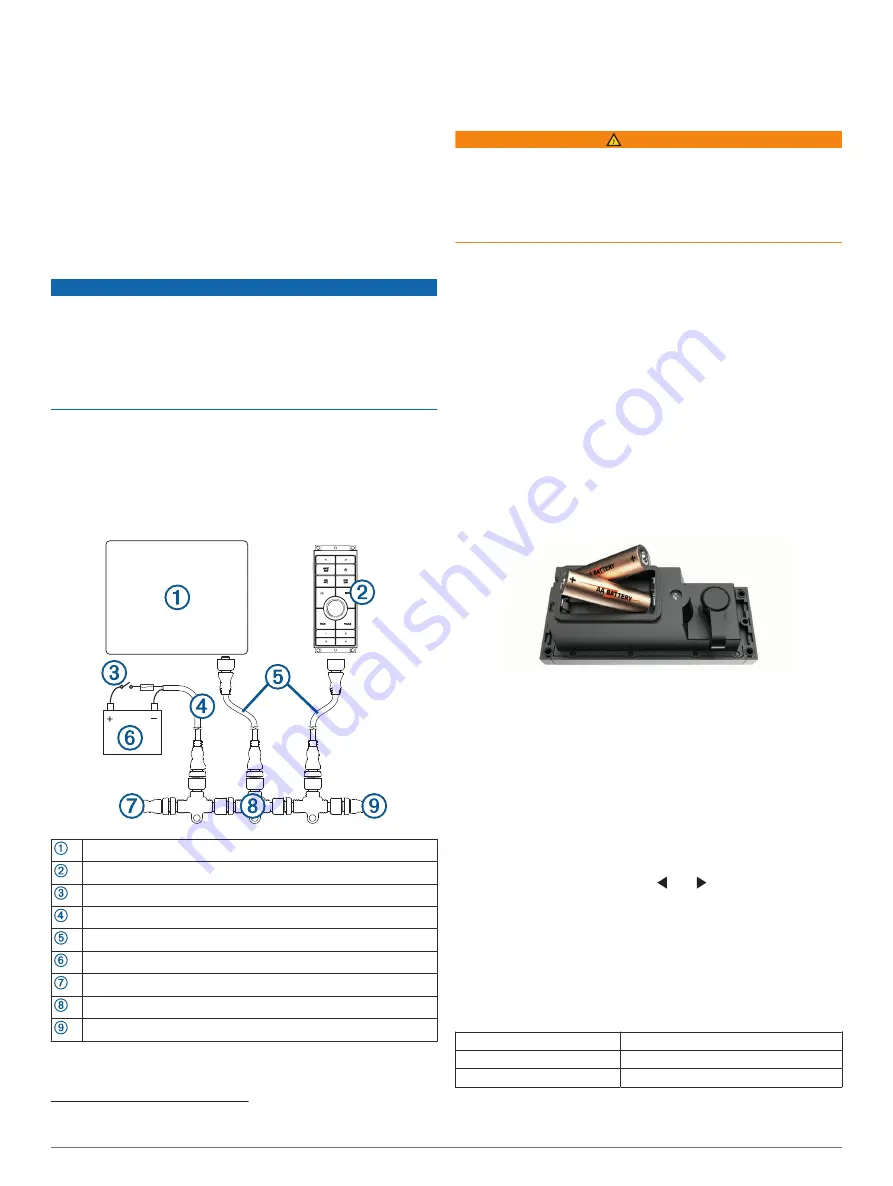
Installing the Batteries
You can use AA alkaline, NiMH, or lithium batteries (not
included). Use lithium batteries for best results.
NOTE:
Do not install batteries if you are using the included
power cable or a NMEA 2000 network connection.
1
Turn the D-ring counter-clockwise, and pull up to open the
battery door.
2
Insert two AA batteries, observing polarity.
NOTE:
You should verify the gasket and battery
compartment are free of debris.
3
Close the battery door, and turn the D-ring clockwise.
After installing batteries, you must pair the device with the
chartplotter (
Pairing the GRID 20 Device with the Chartplotter
Pairing the GRID 20 Device with the Chartplotter
After you supply power to the GRID 20 device, you must pair it
with the chartplotter to make the data connection.
1
On the compatible chartplotter, select
Settings
>
System
>
Station Information
>
GRID™ Pairing
>
Add
.
2
On the GRID 20 device, press and until the device
beeps.
After the GRID 20 device connects to the chartplotter, the GRID
20 device emits a single, long beep.
NOTE:
If the GRID 20 device is the only controller for the
chartplotter and is running on battery power only, you will not be
able to control a connected autopilot with the GRID 20 device.
Specifications
Dimensions (W×H×D)
14.1 × 5.6 × 6.8 cm (5.6 × 2.2 × 2.7 in.)
Material
Fully gasketed, high-impact plastic
Water resistance
IEC 60529 IPX7
1
1
*The device withstands incidental exposure to water of up to 1 m for up to 30 min. For more information, go to
.
3


