Garmin GPSMAP 8000 Series Installation Instructions Manual Download Page 4

• The antenna should not be mounted directly in the path of the 

radar  .

• The antenna should be mounted at least 1 m (3 ft.) away 

from (preferably above) the path of a radar beam or a VHF 
radio antenna  .

Testing the Mounting Location

1

Temporarily secure the antenna in the preferred mounting 

location and test it for correct operation.

2

If you experience interference with other electronics, move 

the antenna to a different location, and test it again.

3

Repeat steps 1–2 until you observe full or acceptable signal 

strength.

4

Permanently mount the antenna.

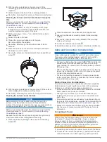
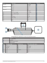
Surface Mounting the Antenna

NOTICE

If you are mounting the bracket on fiberglass with screws, it is 

recommended to use a countersink bit to drill a clearance 

counterbore through only the top gel-coat layer. This will help to 

avoid any cracking in the gel-coat layer when the screws are 

tightened.
Stainless-steel screws may bind when screwed into fiberglass 

and overtightened. Garmin recommends applying an anti-seize 

lubricant to the screws before installing them.

Before you permanently mount the antenna, you must test the 

mounting location for correct operation (

Antenna Mounting 

Considerations

, page 3

).

1

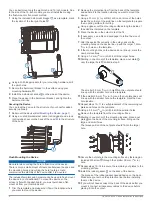
Using the surface-mount bracket   as your mounting 

template, mark the three pilot-hole locations and trace the 

cable-hole in the center of the bracket.

2

Set the surface-mount bracket aside.
Do not drill through the bracket.

3

Drill the three 3.2 mm (

1

/

8

 in.) pilot holes.

4

Use a 25 mm (1 in.) hole saw to cut the cable hole in the 

center.

5

Place the seal pad   on the bottom of the surface-mount 

bracket, aligning the screw holes.

6

Use the included M4 screws to secure the surface-mount 

bracket to the mounting surface.
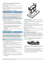
7

Route the cable   through the 25 mm (1 in.) hole and 

connect it to the antenna.

8

Verify the large gasket   is in place on the bottom of the 

antenna, place the antenna on the surface-mount bracket, 

and twist it clockwise to lock it in place.

9

Secure the antenna to the mounting bracket with the included 

M3 set screw  .

10

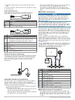
Route the cable away from sources of electronic interference.

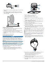
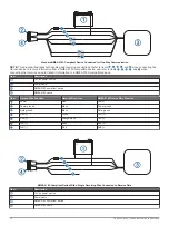
Mounting the Antenna with the Cable Routed Outside the 

Pole

Before you permanently mount the antenna, you must test the 

mounting location for correct operation (

Antenna Mounting 

Considerations

, page 3

).

1

Route the cable through the pole-mount adapter  , and 

place the cable in the vertical slot   along the base of the 

pole-mount adapter.

2

Screw the pole-mount adapter onto a standard 1 in. OD, 14 

threads per inch, pipe-threaded pole (not included).
Do not overtighten the adapter on the pole.

3

Connect the cable to the antenna.

4

Place the antenna on the pole-mount adapter and twist it 

clockwise to lock it in place.

5

Secure the antenna to the adapter with the included M3 set 

screw  .

4

GPSMAP 8000 Series Installation Instructions

Summary of Contents for GPSMAP 8000 Series

Page 1: ...he temperature range for this device is listed in the product specifications Extended exposure to temperatures exceeding the specified temperature range in storage or operating conditions may cause de...

Page 2: ...ng surface for cutting 4 Using a jigsaw cut the mounting surface along the inside of the solid line indicated on the template 5 Place the device in the cutout to test the fit 6 If necessary use a file...

Page 3: ...1 Trim the flush mount template and make sure it fits in the location where you want to mount the device 2 Remove the protective liner from the back of the template and adhere it to the location where...

Page 4: ...e center of the bracket 2 Set the surface mount bracket aside Do not drill through the bracket 3 Drill the three 3 2 mm 1 8 in pilot holes 4 Use a 25 mm 1 in hole saw to cut the cable hole in the cent...

Page 5: ...crews 5 Connect the cable to the antenna 6 Route the cable away from sources of electronic interference Cable and Connection Considerations NOTICE A blue rubber seal is included for each DVI port on t...

Page 6: ...cable NMEA 2000 Considerations NOTICE If you have an existing NMEA 2000 network on your boat it should already be connected to power Do not connect the NMEA 2000 power cable to an existing NMEA 2000 n...

Page 7: ...to NMEA 0183 compliant devices For more information on the NMEA 0183 capabilities of the device see Advanced NMEA 0183 Connections page 8 Standard NMEA 0183 Compliant Device Item Description 12 Vdc po...

Page 8: ...internal port should be connected to the A and B wires of your NMEA 0183 compliant device Refer to the table and wiring diagrams when connecting the data cable to NMEA 0183 devices Consult the install...

Page 9: ...Ground shield Black N A Spare N A N A Spare N A Standard NMEA 0183 Compliant Device Connected for Two Way Communication Item Description 12 Vdc power source Power cable NMEA 0183 compliant device NME...

Page 10: ...compatible device Item Description 12 Vdc power source Power cable NMEA 0183 compliant device NMEA 0183 cable Item Garmin Wire Function Garmin Wire Color NMEA 0183 Device Wire Function Power Red Powe...

Page 11: ...ound Black Data ground RxB Orange white N A RxA White TxA Lamp or Horn Connections The device can be used with a lamp a horn or both to sound or flash an alert when the chartplotter displays a message...

Page 12: ...e If needed you can use a VGA to DVI I adapter to connect a VGA source to this port You can connect a display to the DVI I VIDEO OUT port to view a mirror image of the screen on a computer monitor or...

Page 13: ...A Max current draw at 12 Vdc 2 8 A Compass safe distance 310 mm 12 2 in Twelve Inch Models Specification Measurement Dimensions W H D 333 247 97 mm 137 64 923 32 313 36 in Display size W H 245 184 mm...

Page 14: ...GPGLL GLL Geographic position latitude and longitude GPGSA GSA GNSS DOP and active satellites GPGSV GSV GNSS satellites in view GPRMB RMB Recommended minimum navigation information GPRMC RMC Recommen...

Reviews: