


Selecting a Different Radar Source
1
Select an option:
• From a radar screen or the radar overlay, select
Menu
>
Radar Setup
>
Source
.
• Select
Settings
>
Communications
>
Preferred
Sources
>
Radar
.
2
Select the radar source.
Autopilot
WARNING
You can use the autopilot feature only at a station installed next
to a helm, throttle, and helm control device.
You are responsible for the safe and prudent operation of your
vessel. The autopilot is a tool that enhances your capability to
operate your boat. It does not relieve you of the responsibility of
safely operating your boat. Avoid navigational hazards and
never leave the helm unattended.
Always be prepared to promptly regain manual control of your
boat.
Learn to operate the autopilot on calm and hazard-free open
water.
Use caution when operating the autopilot near hazards in the
water, such as docks, pilings, and other boats.
The autopilot system continuously adjusts the steering of your
boat to maintain a constant heading (heading hold). The system
also allows manual steering and several modes of automatic-
steering functions and patterns.
Opening the Autopilot Screen
Before you can open the autopilot screen, you must have a
compatible autopilot installed and configured.
Select
A/V, Gauges, Controls
>
Autopilot
.
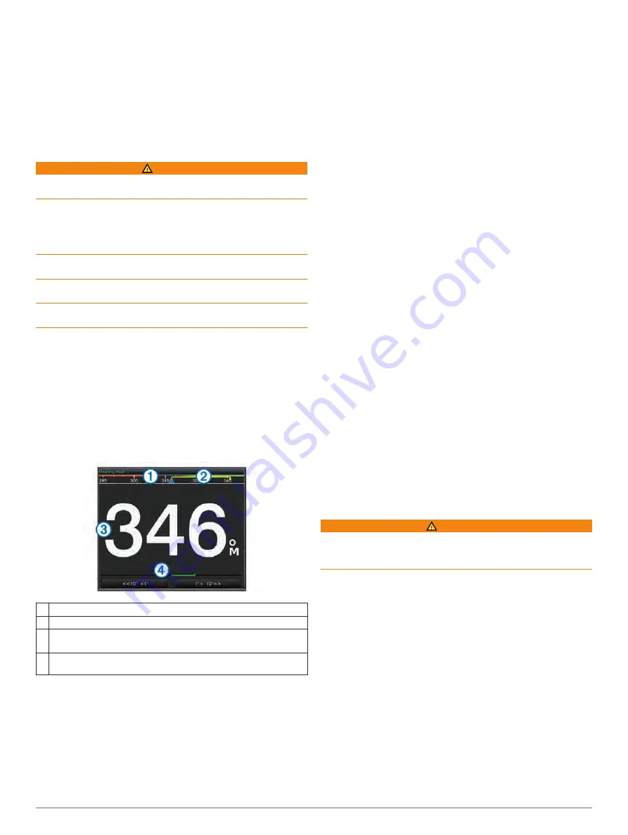
Autopilot Screen
À
Actual heading
Á
Intended heading (heading the autopilot is steering toward)
Â
Actual heading (when in standby mode)
Intended heading (when engaged)
Ã
Rudder position indicator (This functionality is available only when a
rudder sensor is connected.)
Adjusting the Step Steering Increment
1
From the Autopilot screen, select
Menu
>
Autopilot Setup
>
Steering Mode
>
Step Turn Size
.
2
Select an increment.
Setting the Power Saver
You can adjust the level of rudder activity.
1
From the autopilot screen, select
Menu
>
Autopilot Setup
>
Power Saver
.
2
Select a percentage.
Selecting a higher percentage reduces rudder activity at the
expense of heading performance. The higher the percentage,
the more the course deviates before the autopilot corrects it.
TIP:
In choppy conditions at low speeds, increasing the
Power Saver percentage reduces rudder activity.
Enabling Shadow Drive
™
NOTE:
The Shadow Drive feature is available only on hydraulic
steering systems.
From the autopilot screen, select
Menu
>
Autopilot Setup
>
Shadow Drive
>
Enabled
.
Engaging the Autopilot
When you engage the autopilot, the autopilot takes control of the
helm and steers the boat to maintain your heading.
From any screen, select
Engage
.
Your intended heading shows in the center of the Autopilot
screen.
Adjusting the Heading with the Helm
NOTE:
You must enable the Shadow Drive feature before you
can adjust the heading using the helm (
With the autopilot engaged, manually steer the boat.
The autopilot activates Shadow Drive mode.
When you release the helm and manually maintain a specific
heading for a few seconds, the autopilot resumes a heading
hold at the new heading.
Adjusting the Heading with the Chartplotter in Step
Steering Mode
Before you can steer your boat using the keys at the bottom of
the autopilot screen, you must engage the autopilot (
• Select
<1°
or
1°>
to initiate a single 1° turn.
• Select
<<10°
or
10°>>
to initiate a single 10° turn.
• Hold
<1°
or
1°>
to initiate a rate-controlled turn.
The boat continues to turn until you let go of the key.
• Hold
<<10°
or
10°>>
to initiate a sequence of 10° turns.
Steering Patterns
WARNING
You are responsible for the safe operation of your boat. Do not
begin a pattern until you are certain that the water is clear of
obstacles.
The autopilot can steer the boat in preset patterns for fishing,
and it can also perform other specialty maneuvers such as U-
turns and Williamson turns.
Following the U-Turn Pattern
You can use the u-turn pattern to turn the boat around 180° and
maintain the new heading.
1
From the autopilot screen, select
Menu
>
Pattern Steering
>
U-Turn
>
Engage
.
2
Select
Engage Port
or
Engage Starboard
.
Setting Up and Following the Circles Pattern
You can use the circles pattern to steer the boat in a continuous
circle, in a specified direction, and at a specified time interval.
1
From the autopilot screen, select
Menu
>
Pattern Steering
>
Circles
.
2
If necessary, select
Time
, and select a time for the autopilot
to steer one complete circle.
3
Select
Engage Port
or
Engage Starboard
.
Autopilot
25
Summary of Contents for GPSMAP 7400 Series
Page 1: ...GPSMAP 7400 7600 Series Owner s Manual February 2015 Printed in Taiwan 190 01841 00_0B...
Page 2: ......
Page 51: ......