background image

44 

GPSMAP

®

 400 Series Owner’s Manual

I

nStallInG


the

 u

nIt

Mounting the Transducer on a Transom

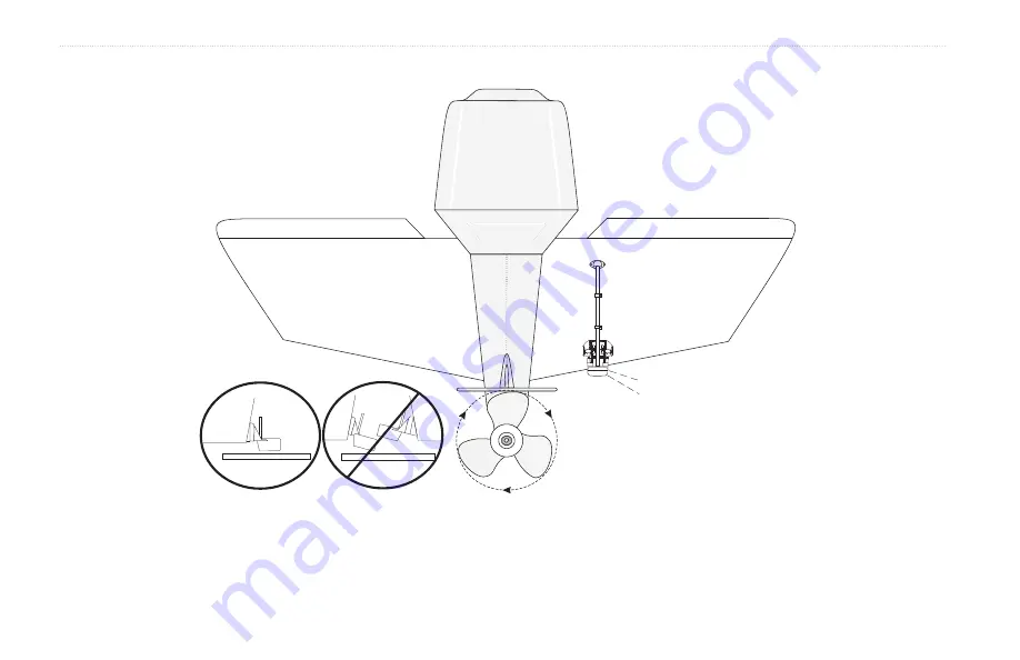
Do not mount the transducer directly in the  
path of the prop. The transducer can cause  
cavitation that may degrade the boat’s  
performance and damage the prop. 

Make sure that the transducer is below  
water level when the boat is on plane  
at high speed. 

Apply marine sealant to all 
screw threads to prevent water 
from seeping into the transom. 

Mount the transducer cable  
cover well above the  
waterline. 

Transducer should extend 
1/8

"

below fiberglass hull or  

3/8

"

below aluminum hull.  

OK

Mount the transducer parallel with the bottom. 

USS Barnett

Summary of Contents for GPSMAP 400 series

Page 1: ...GPSMAP 400 series owner s manual ...

Page 2: ...vided that such electronic or printed copy of this manual must contain the complete text of this copyright notice and provided further that any unauthorized commercial distribution of this manual or any revision hereto is strictly prohibited Information in this document is subject to change without notice Garmin reserves the right to change or improve its products and to make changes in the conten...

Page 3: ...pear in the text They indicate that you should highlight a series of items on the screen using the ROCKER and press the SELECT key after each item For example if you see select Charts Navigation Chart you should highlight Charts and press SELECT Then highlight Navigation Chart and press SELECT again Quick Links Turning the Unit On or Off page 2 Acquiring GPS Satellite Signals page 4 Inserting and ...

Page 4: ... Using Charts 7 Using the Navigation Chart 7 Using BlueChart g2 Vision 11 Using Mariner s Eye 3D 12 Using Fish Eye 3D 13 Using Fishing Charts 13 Enabling High Resolution Satellite Imagery 14 Viewing Aerial Photos 15 Viewing Current Station Information 16 Detailed Road and POI Data 16 Using Automatic Guidance 16 Changing the Chart Settings 16 Using the Chart Sonar Screen 18 Where To 19 Navigating t...

Page 5: ...plit Zoom Screen 36 Understanding the Temp Log Screen 37 Setting Up Sonar 37 Advanced Sonar Settings 38 Installing The Unit 39 Step 1 Select a Location 39 Step 2 Mount the Unit 40 Step 3 Install the Transducer 42 Step 4 Install the Wiring Harness 48 Step 5 Test the Installation 51 Appendix 53 Specifications 53 Product Registration 54 Caring for the Unit 54 Alarms and Messages 55 Weather Data Warra...

Page 6: ... State of California to cause cancer birth defects or reproductive harm This Notice is provided in accordance with California s Proposition 65 See www garmin com prop65 for more information Warnings Important Information MAP DATA INFORMATION One of the goals of Garmin is to provide customers with the most complete and accurate cartography that is available to us at a reasonable cost We use a combi...

Page 7: ...GPSMAP 400 Series Owner s Manual Getting Started Getting Started Unit Overview SELECT MARK MENU HOME SD card slot External GPS antenna GPSMAP 440sx Shown GXM 31 antenna Power data ...

Page 8: ... Garmin screen appears When the Warning screen appears press SELECT to open the Home screen Note The first time you power on your unit you must go through a setup sequence See page 51 for details Adjusting the Backlight 1 Press and release the POWER key 2 Select Light Press left or right on the ROCKER to manually adjust the backlight ...

Page 9: ...nd hold to turn the unit on or off press and release to adjust the backlight and Day Night modes RANGE Press to adjust the range of the sonar zoom in or out on a chart ROCKER Press up down left or right to move through menus highlight fields and enter data MARK Press to mark a waypoint SELECT Press to select highlighted items and confirm on screen messages HOME Press to return to the Home screen M...

Page 10: ...s the green bars disappear For more information about GPS visit the Garmin Web site at www garmin com aboutGPS Using Simulator Mode Simulator Mode turns the GPS receiver off for use indoors or for practice The unit does not track satellites in Simulator Mode Caution Do not try to navigate using Simulator Mode because the GPS receiver is turned off Any satellite signal strength bars shown are only ...

Page 11: ...ay need this information to update the system software or purchase additional map data information From the Home screen select Configure System System Information Inserting and Removing SD Cards Your unit supports Secure Digital SD cards Insert optional BlueChart g2 Vision SD cards to view high resolution satellite imagery and aerial reference photos of ports harbors marinas and other points of in...

Page 12: ...0s 430x 430sx units do not need additional cards to use the Fish Eye 3D charts and do not have the option to use the Fishing Chart all depth contours and depth soundings are available on the Navigation Chart Sonar access sonar information page 35 Note This option is available only if you have a unit with a built in sounder or a Garmin sonar module connected Chart Sonar set up the screen to view a ...

Page 13: ...ion preprogrammed SD cards Fishing Chart removes navigational data from the preloaded map while leaving the bottom contours and depth soundings This is not available on the 430 430s 430x 430sx all contour lines and depth soundings appear on the navigation chart Fish Eye 3D an underwater view that visually represents the sea floor or lake bottom according to the chart s information This is availabl...

Page 14: ...urn NEXRAD weather data on or off Note You must plug the optional GXM 31 antenna into the XM port on the back of the unit and have a subscription to XM WX Satellite Weather to view NEXRAD data XM is only available on the GPSMAP 430x 430sx 440x 440sx units For more information on XM weather see the GXM 31 Owner s Manual Overlay Numbers show or hide cruising sailing navigation and fishing numbers on...

Page 15: ...atures common to most charts include depth contour lines with deep water represented in white intertidal zones spot soundings as depicted on the original paper chart navigational aids and symbols and obstructions and cable areas Panning the Navigation Chart Use the map pointer to pan away from your current location and scroll to other areas on the navigation chart As you pan past the edge of the c...

Page 16: ...he number represents that distance on the map Accessing Additional Object Information Use the map pointer to view information about on screen map items and waypoints To access additional object information 1 On the navigation chart highlight an item with the map pointer and press SELECT Selected item 2 Select the item If more than one item is in the area select Review and then select the item ...

Page 17: ...t for a more visual navigation aid The BlueChart g2 Vision Mariner s Eye 3D is more detailed than the preloaded data Fish Eye 3D an underwater view that visually represents the sea floor according to the chart s information Fishing Charts view the chart without navigational data leaving only the bottom contours and depth soundings This chart works best for offshore deep sea fishing High Resolution...

Page 18: ...ner s Eye 3D Settings To access additional settings or options from the Mariner s Eye 3D screen press MENU Colors choose between Normal Default Water Hazard and All Hazard The Normal setting highlights the land as you would see it from the water The Hazard settings indicates shallow water and land with a color scale Blue indicates deep water yellow is shallow water and red is very shallow The Wate...

Page 19: ... or off Numbers show or hide cruising navigation or fishing numbers on the chart Using Fishing Charts Use the fishing chart for a detailed unobstructed view of the bottom contours and depth soundings on the chart The fishing chart uses detailed bathymetric data on the BlueChart g2 Vision SD card and works best for offshore deep sea fishing To view the fishing chart from the Home screen select Char...

Page 20: ...following options Off standard chart information is shown on the map Land Only standard chart information is shown on water with photos overlaying the land On photos overlay both the water and the land at a specified opacity The higher you set the percentage the more the satellite photos will cover both land and water NOTE When enabled the high resolution satellite images are only present at lower...

Page 21: ...help orient yourself to your surroundings or to help acquaint yourself with a marina or harbor prior to arrival Aerial Photo Note Use the RANGE keys to zoom in and out while viewing the aerial photo on the full screen To access aerial photos from the navigation chart Select Aerial Photo On the navigation chart use the ROCKER to highlight a camera with the pointer Select View Fullscreen Perspective...

Page 22: ...on beginning on page 19 Using Automatic Guidance Automatic Guidance automatically creates and suggests passage based on available BlueChart g2 Vision chart information See page 32 for instructions on setting up Automatic Guidance for your boat The Where To section on page 19 has more information on how to use Automatic Guidance Changing the Chart Settings To change chart settings from the Home scr...

Page 23: ...racks on the chart Appearance customize how items are shown on the map Changing the Chart Appearance From the Home screen select Charts Chart Setup Appearance Detail adjust the amount of detail shown on the map Press right on the ROCKER to increase map detail Press left on the ROCKER to decrease map detail Photos set the high resolution satellite images to on off or land only See page 14 for more ...

Page 24: ...ew a split chart sonar screen 1 From the Home screen select Chart Sonar 2 Select the type of chart on the split screen Navigation chart screen Navigation Sonar Combination Sonar screen To access additional settings or options for the chart sonar screen press MENU Mariner s Eye 3D Sonar Note The Chart Sonar screen like the Sonar screen is only available when using a sonar capable unit with a transd...

Page 25: ...g you to add turns to the route Guide To searches BlueChart g2 Vision chart data to suggest the best path to your destination Caution Guide To does not assure obstacle and bottom clearance For safety always resolve any discrepancies or questions before continuing navigation Navigating to a Destination You can search for and navigate to nearby destinations including fuel repairs marinas waypoints a...

Page 26: ...g a preprogrammed BlueChart g2 Vision card to use Auto Guidance 6 Follow the colored line on the screen to the destination To stop navigating Press MENU and then select Stop Navigating To search for a destination by name 1 From the Home screen select Where To Search by Name 2 Press up or down on the ROCKER to select a number or character press left or right to move fields 3 Press SELECT to view th...

Page 27: ...ional MOB symbol is created and the unit is on an active navigation to that point To mark your location 1 From any screen press MARK 2 Select Back to return to the chart or select MOB to designate the waypoint as an MOB point Note Pressing the MARK key only creates a waypoint at your present location To create a new waypoint 1 Move the map pointer to the location you want and press SELECT 2 Select...

Page 28: ...int 3 Select the waypoint attribute you want to change Name Symbol Depth Water Temp or Position To move the waypoint on the navigation chart 1 Select Edit Waypoint Position Use Chart 2 Use the ROCKER to move the waypoint to a different location and press SELECT To view a list of all waypoints From the Home screen select Information User Data Waypoints ...

Page 29: ...Adding a Turn to a Route 3 Use the ROCKER to add a turn and press SELECT Repeat this step to add additional turns 4 Press MENU to cancel or to begin navigating the route To create a route in another location 1 From the Home screen select Information User Data Routes New Route Creating a New Route 2 Use the ROCKER to select the route s starting point and press SELECT 3 Use the ROCKER and SELECT key...

Page 30: ...select Information User Data Routes 2 Select the route to edit 3 Select Edit Route You can edit the route name turns or delete the route To delete a route 1 From the Home screen select Information User Data Routes 2 Select the route to delete and then select Edit Route 3 Select Delete ...

Page 31: ...ormation and navigation information You can customize the number of fields shown and the type of information shown in each field You can display up to six fields of numerical information To view the numbers screen from the Home screen select Information Numbers To customize the numbers screen 1 From the Home screen select Information Numbers 2 Press Menu and then press SELECT 3 Select the number o...

Page 32: ...ect Show Report To return to the Tide Prediction Chart select Show Tide Chart Viewing Current Information Use the Current Prediction screen to view information for currents To view current prediction information select Currents from the Information screen then select a Current Station from the list Flood Current current heading toward shore Ebb Current current heading away from shore Max level Max...

Page 33: ...ta Waypoints view a list of all saved waypoints Routes view a list of saved routes Tracks view a list of saved tracks Data Transfer transfer waypoints routes and tracks to and from an SD card Clear User Data erase all user waypoints routes and tracks To transfer data to or from an SD card 1 Insert an SD card into the SD card slot on the front of the unit 2 From the Home screen select Information U...

Page 34: ...SC Log view a list of all DSC calls sorted by most recent sender or by type distress calls or position reports View Most Recent view the seven most recent DSC calls received sorted and displayed chronologically by time and date Calls with identical time and date information show the same information in the list View By Sender view an alphanumerical list of senders View By Type view the seven most ...

Page 35: ...styles for Wind and Next Turn numbers Changing Units of Measure To change units of measure from the Home screen select Configure Units System Units this is a quick global setting that defines most of the individual units of measure listed below at once Statute mh ft ºF Metric kh m ºC or Nautical kt ft ºF Depth individually set the units of measure for depth to Feet ft Fathoms fa or Meters m Temper...

Page 36: ...rd NMEA 0183 data DSC and sonar NMEA input support for the DPT MTW and VHW sentences NMEA High Speed supports the input or output of standard 0183 data for most AIS receivers None provides no interfacing capabilities NMEA Setup enable or disable NMEA output sentences for sounder route system and Garmin NMEA settings To enable or disable NMEA output sentences 1 From the Home screen select Configure...

Page 37: ...avigation Alarms To set a navigation alarm from the Home screen select Configure Alarms Navigation Anchor Drag set an alarm to sound when you exceed a specified drift distance Arrival set an alarm to sound when you are within a specified distance or time from a destination waypoint Off Course set an alarm to sound when you are off course by a specified distance Setting System Alarms To set a syste...

Page 38: ...iew weather information XM Weather is available only on GPSMAP 430x 430sx 440x 440sx units See the GXM 31 Owner s Manual for more information Configuring My Boat To configure settings for your boat from the Home screen select Configure My Boat Auto Guidance set the Auto Guidance parameters for your boat Safe Depth set the minimum depth referred to the chart depth datum to allow when calculating an...

Page 39: ...rd Garmin transducer and should only be used to match the specifications of a non standard transducer Calibrate Water Speed to use a speed sensing transducer use this menu to calibrate the speed sensor If you do not have a speed sensing transducer this menu does not appear To calibrate the speed sensor 1 From the Home screen select Configure My Boat Transducer Calibrate Water Speed 2 Bring the boa...

Page 40: ...TE To configure AIS or DSC information for other boats your unit must be connected to an external AIS or DSC device See page 30 for more information Safe Zone turn a safe zone around your boat on or off This is used for collision avoidance and can be customized Ring show or hide a ring on the map showing the safe zone for your boat Range change the measured radius of the safe zone ring to a specif...

Page 41: ...nar Full Screen Transducer frequency or beam width Temperature Speed Depth Range Suspended targets Understanding the Flasher The Flasher screen dual beam transducer only provides an almost instantaneous return of what is below your boat The depth scale is organized as a ring that starts at the top or 12 00 and progresses clockwise Sonar information flashes on the ring when it is received at the de...

Page 42: ...frequency graph appears on the right To open the Split Freq screen from the Home screen select Sonar Split Freq Depth temperature and speed Range Frequencies Understanding The Split Zoom Screen Use the Split Zoom screen to view the full sonar data from the graph and a zoomed in portion on the same screen From the Home screen select Sonar Split Zoom Transducer frequency or beam width Depth temperat...

Page 43: ...st settings universal to all sonar screens From the Home screen select Sonar Sonar Setup Color Scheme choose white or blue This affects the background on all sonar screens but does not change the Temp Log screen Fish Symbols set how the sonar interprets suspended targets The unit does not interpret the sonar return data default Suspended targets appear as symbols Background sonar information appea...

Page 44: ... To show water temperature or water speed change the setting to Auto If the connected transducer is capable the data is shown Advanced Sonar Settings To adjust advanced sonar settings press MENU while viewing a sonar screen Range the range of the depth scale on the right side of the screen Auto or Manual Range Gain controls the sensitivity of the sonar receiver Auto or Manual Gain To see more deta...

Page 45: ...ep 1 Select a Location Consider the following when you select an installation location Provides optimal viewing as you operate your boat Allows easy access to the unit s keypad Is strong enough to support the weight of the unit and protect it from excessive vibration or shock Allows room for the routing and connection of the power data and transducer cables There should be at least a 3 inch 8 cm c...

Page 46: ...le for mounting in exposed locations or at the navigation station The unit comes with a tilt swivel mounting bracket that can be used for console mounting Mounting the Bracket Assembly Tools not included drill screwdriver Phillips or standard and one of the following Three 8 4 mm pan head machine bolts with matching nuts and washers and a 5 32 5 mm drill bit Three 8 pan head self tapping screws an...

Page 47: ...O NOT OVERTIGHTEN 4 Place the swivel mount bracket over the swivel base and secure it with the short knob To install the unit on the mounting bracket 1 Align the slot on the back of the unit with the long mounting knob and slide the unit into place If necessary adjust the long knob to spread the bracket arms apart Turn counter clockwise to widen the bracket arms and clockwise to tighten 2 Adjust t...

Page 48: ...n instructions for some popular transducers Detailed installation instructions are provided in the transducer kits Some transducers might have to be installed by a professional marine installer To assemble the transducer 1 Insert the rubber washer and plastic spacer into the transducer at the same time DO NOT lubricate the rubber washer 2 Route the cable toward the back of the transducer Slide the...

Page 49: ...r body Place the pointed end of the cable tie through the fastener hole on the opposite end and pull it through until it is snug but not tight The cable tie clicks when you pull it 5 Position the transducer so that it is parallel with the bottom when in use and make sure the gasket is aligned properly Pull the cable tie end until tight Trim off the excess if necessary Tighten the 10 32 locking nut...

Page 50: ...oat s performance and damage the prop Make sure that the transducer is below water level when the boat is on plane at high speed Apply marine sealant to all screw threads to prevent water from seeping into the transom Mount the transducer cable cover well above the waterline Transducer should extend 1 8 below fiberglass hull or 3 8 below aluminum hull OK Mount the transducer parallel with the bott...

Page 51: ... The transducer must be in clean non turbulent water for optimal performance Tool List not included drill 3 8 wrench or socket 5 32 and 1 8 drill bits masking tape 2 Phillips screwdriver and marine sealant To mount the transducer on a transom 1 Position the transducer mount at the selected transom location Make sure the transducer is parallel with the water line Mark the center locations of each h...

Page 52: ...ll Installation To avoid drilling a hole to mount a thru hull transducer a transducer can be secured with epoxy inside a boat shoot thru hull installation This type of installation can provide better noise reduction and allow you to use a higher Gain setting For a transducer to be mounted inside the hull shoot thru not thru hull the boat must be fiberglass with no core Contact your boat manufactur...

Page 53: ...ollowing illustration 2 Temporarily seal the test device to the hull with caulking or RTV sealer and fill with water or light mineral oil 3 Place the transducer in the water pointed directly at the bottom and weight it down Set the unit for optimum performance If the sonar performance is significantly degraded another location must be tested Testing the Location PVC pipe or a can Weight the transd...

Page 54: ...The maximum unit input voltage is 35 Volts DC Do not exceed this voltage because this can damage the unit and void the warranty Note During a typical installation use only the Red and Black wires The other wires do not have to be connected for normal operation of the unit For information on connecting to a NMEA or CANet compatible device see page 50 To install the wiring harness 1 Use a test light...

Page 55: ...y On BLUE NMEA 1 Out BROWN NMEA 1 In GREY NMEA 2 Out GREEN CANet L WHITE CANet H YELLOW Alarm Low VIOLET NMEA 2 In Alarm Relay 100ma max coil current To Transducer GPSMAP 400 Series Wiring Harness PIN 8 Black Ground PIN 13 Red DC Positive PIN 7 Yellow Alarm PIN 12 White CANet H PIN 16 Green CANet L PIN 18 Blue NMEA Out GPSMAP 400 Series Pin Assignment ...

Page 56: ...igation device You must set the unit s serial port s to NMEA In NMEA Out to send data and receive data page 30 The SDDBT SDDPT SDMTW SDVHW SDWPL sentences are sent and received in NMEA 0183 Version 3 01 You can purchase complete information about National Marine Electronics Association NMEA format and sentences from NMEA Seven Riggs Avenue Severna Park MD 21146 USA www nmea org Installing the Unit...

Page 57: ...on Format the default is hddd mm mmm 5 Select the Time Format the default is 12 Hour 6 Select your Time Zone 7 Select your preferred Units of measure 8 Select Minimum Depth 9 Select the Overhead Clearance of your boat The Home screen appears see page 6 after you select your configuration options Note You can adjust these options in the future from the Configure screen Because water is necessary to...

Page 58: ...t which the signal was lost Make moderate turns in both directions and see if the signal improves 3 If the signal strength improves while turning adjust the transducer so that it extends another 1 8 below the transom of the boat It might take several adjustments to eliminate the degradation 4 If the signal does not improve you might have to move the transducer to a different location NOTE When adj...

Page 59: ...econds AutoLocate Approx 2 minutes Update Rate 1 second continuous GPS Accuracy Position 49 feet 15 meters 95 typical Velocity 0 05 meters sec steady state WAAS Accuracy Position 10 feet 3 meters 95 typical Velocity 0 05 meters sec steady rate Dynamics 6gs Subject to accuracy degradation to 100 m 2DRMS under the U S DOD imposed Selective Availability Program Power Power Source 10 35 VDC Usage 15 W...

Page 60: ...g for the Unit The case is constructed of high quality materials and does not require user maintenance except cleaning Cleaning the Case Clean the unit s outer casing except for the screen using a cloth dampened with a mild detergent solution and then wipe dry Avoid chemical cleaners and solvents that may damage plastic components Cleaning the Screen The unit s lens is coated with a special anti r...

Page 61: ... input voltage to 35 Volts or less Boat Is Not Moving Fast Enough to Calibrate the boat is not moving fast enough for the speed wheel to provide a valid speed Can t Read User Card error reading card remove and reinsert Contact your dealer or Garmin Product Support if the problem persists Can t Read Voltages That High Limited To Top Of Range the voltage value in the Battery Alarm setup is higher th...

Page 62: ...e temperature specified by the Water Temperature Alarm These messages appear when you enter or leave that zone Fish Alarm a beep sounds if enabled when a fish is detected This alarm does not show a message banner Flash Flood Warning a flash flood warning was issued for the area by the National Weather Service Flood Warning a flood warning was issued for the area by the National Weather Service Inv...

Page 63: ...ar Timeout there is an internal problem with the unit Contact your dealer or Garmin Product Support to have the unit serviced Sonar Service Lost the external sonar device you were connected to has either been disconnected or the unithas lost communication with the sonar device for some other reason Tornado Warning a tornado warning was issued for the area by the National Weather Service Track Alre...

Page 64: ...s not detected Check the connections Water Temperature Alarm sonar has reported a temperature above below inside or outside the specified value s Waypoint Already Exists you entered a waypoint name that already exists in memory Modify the waypoint name or delete the existing waypoint Waypoint Memory Full you have used all 1 500 waypoints available Delete unwanted waypoints to make space for new en...

Page 65: ...interruptions in the transmission or reception of the Services LIMITS ON OUR RESPONSIBILITY a DISCLAIMERS EXCEPTAS EXPRESSLY PROVIDED HEREIN WE MAKE NO WARRANTY OR REPRESENTATION EITHER EXPRESS OR IMPLIED REGARDING THE RADIO SERVICE YOUR USE OF THE SERVICE IS AT YOUR SOLE RISK THE CONTENTAND FUNCTIONALITY OF THE SERVICE IS PROVIDED AS IS WITHOUTANY WARRANTY OF ANY KIND EXPRESS OR IMPLIED ALL SUCH ...

Page 66: ...bject to Customer Agreement included with the XM Welcome Kit and available at xmradio com Available only in the 48 contiguous United States XM WX is a trademark of XM Satellite Radio Inc Software License Agreement BY USING THE UNIT YOU AGREE TO BE BOUND BY THE TERMS AND CONDITIONS OF THE FOLLOWING SOFTWARE LICENSE AGREEMENT PLEASE READ THIS AGREEMENT CAREFULLY Garmin grants you a limited license t...

Page 67: ...ur local Garmin authorized dealer or call Garmin Product Support for shipping instructions and an RMA tracking number Securely pack the unit and a copy of the original sales receipt which is required as the proof of purchase for warranty repairs Write the tracking number clearly on the outside of the package Send the unit freight charges prepaid to any Garmin warranty service station Online Auctio...

Page 68: ...nna Increase the separation between the equipment and the receiver Connect the equipment into an outlet that is on a different circuit from the GPS unit Consult the dealer or an experienced radio TV technician for help This product does not contain any user serviceable parts Repairs should only be made by an authorized Garmin service center Unauthorized repairs or modifications could result in perm...

Page 69: ...ngs 16 D Declaration of Conformity 62 depth 29 depth line 38 DSC 28 34 E event log 29 F fish eye 3D 13 settings 13 fishing chart 13 fish symbols 37 flush mount 40 frequency 38 fuse 48 53 G gain 38 go to 19 GPS wiring to a 50 guide to 19 H heading 29 HOME key 3 I input voltage 48 installing 39 48 selecting a location 39 testing 51 the mount 40 the transducer 42 the wiring harness 48 to a Garmin CAN...

Page 70: ...ations 53 specifications 53 speed sensor 33 spot depths 17 surface mounting the unit 40 surface noise 38 suspended targets 37 swivel base 41 swivel mount bracket 41 symbols 9 system information viewing 5 T temperature 29 test the installation 51 tide stations 26 viewing information 11 time 29 transducer 46 cables 39 dual beam 33 35 dual frequency 33 36 38 installing 42 45 transom 45 transom mounti...

Page 71: ......

Page 72: ...t www garmin com 2007 Garmin Ltd or its subsidiaries Garmin International Inc 1200 East 151st Street Olathe Kansas 66062 USA Garmin Europe Ltd Liberty House Hounsdown Business Park Southampton Hampshire SO40 9RB UK Garmin Corporation No 68 Jangshu 2nd Road Shijr Taipei County Taiwan www garmin com Part Number 190 00754 00 Rev B ...

Reviews: