Page 5-10
500 SERIES INSTALLATION MANUAL
Rev Q
190-00181-02
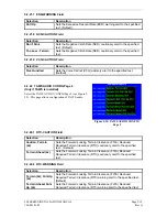
5.2.9 MAIN CDI/OBS CONFIG Page
Select the MAIN CDI/OBS CONFIG Page (see Figure 5-
11). This page allows you to verify the MAIN CDI
outputs, both lateral (
LAT
) and vertical (
VERT
), and
verify and calibrate the MAIN OBS input. Using the
controls on the 500 Series unit front panel, make the
selections below and verify the interfaces as appropriate:
CDI (LAT/VERT)
Selection Verify
That:
Max left/up
The CDI is “pegged” to the left/up.
Full left/up
The CDI is deflected full scale to the left/up.
Center
The CDI is centered.
Full right/down
The CDI is deflected full scale to the right/down.
Max right/down
The CDI is “pegged” to the right/down.
NAV FLAG (LAT/VERT)
Selection Verify
That:
Hidden
The LAT/VERT flag is hidden.
In view
The LAT/VERT flag is in view.
TO-FROM
Selection Verify
That:
FROM
The FROM flag is in view.
Hidden
The TO/FROM flag is hidden.
TO
The TO flag is in view.
SELECTED COURSE
Select 150° on the CDI/HSI that is connected to the 500 Series unit’s MAIN OBS inputs. The
SELECTED COURSE
field should indicate near to 150° and a
Calibrate to 150°?
field appears.
Selecting this field calibrates the 500 Series unit to match the input source. Verify OBS operation by
checking that the course displayed on the 500 Series unit is within 2° of the selected course. Do this at 30°
intervals around the OBS card.
NOTE
If it is desired to ignore a selected course input (either analog resolver or ARINC 429)
for GPS operation in OBS mode, press MENU on the MAIN CDI/OBS CONFIG page
and select “Ignore SEL CRS or GPS?”. When OBS mode is selected, the selected course
is entered on the controls of the 500 Series unit. If ignoring the selected course input
such that the VOR valid flag is dependent only on a valid VOR signal, with lateral
deviation calculated by another display device, press MENU on the MAIN CDI/OBS
CONFIG page and select “Ignore SEL CRS for VLOC?”.
Figure 5-11.
MAIN CDI/OBS CONFIG Page
Summary of Contents for GPS 500
Page 52: ...Page 4 26 500 SERIES INSTALLATION MANUAL Rev Q 190 00181 02 This page intentionally left blank...
Page 80: ...Page 5 28 500 SERIES INSTALLATION MANUAL Rev Q 190 00181 02 This page intentionally left blank...
Page 84: ...Page A 4 500 SERIES INSTALLATION MANUAL Rev Q 190 00181 02 This page intentionally left blank...
Page 86: ...Page B 2 500 SERIES INSTALLATION MANUAL Rev Q 190 00181 02...
Page 87: ...500 SERIES INSTALLATION MANUAL Page B 3 190 00181 02 Rev Q...
Page 88: ...Page B 4 500 SERIES INSTALLATION MANUAL Rev Q 190 00181 02...
Page 89: ...500 SERIES INSTALLATION MANUAL Page B 5 190 00181 02 Rev Q...
Page 90: ...Page B 6 500 SERIES INSTALLATION MANUAL Rev Q 190 00181 02...
Page 91: ...500 SERIES INSTALLATION MANUAL Page B 7 190 00181 02 Rev Q...
Page 92: ...Page B 8 500 SERIES INSTALLATION MANUAL Rev Q 190 00181 02...
Page 93: ...500 SERIES INSTALLATION MANUAL Page B 9 190 00181 02 Rev Q...
Page 94: ...Page B 10 500 SERIES INSTALLATION MANUAL Rev Q 190 00181 02...


