


Av. Kit Install. Manual
190-00026-00 Rev. Q
Page 12
With power applied to the aviation rack and the GPS 150 unit off, continuously
depress the ENT key and turn the unit on (release the ENT key when the display
activates). Rotate the outer knob, and the CDI Test Page will be displayed. Using the
controls on the GPS 150 front panel, make the selections indicated below and verify
the interfaces as appropriate:
CDI
Full scale left
Ensure the CDI is deflected full scale left (5 dots)
Full scale right
Ensure the CDI is deflected full scale right (5 dots)
C e n t e r e d
Ensure the CDI is centered
Maximum scale left
Ensure the CDI is deflected beyond full scale left
Maximum scale right
Ensure the CDI is deflected beyond full scale right
T O / F R O M / F L A G
TO
Ensure TO flag is visible
FROM
Ensure FROM flag is visible
FLAG
Ensure TO and FROM are NOT visible
CDI FLAG
IN VIEW
Ensure CDI flag is in view
OUT OF VIEW
Ensure CDI flag is out of view
SUPERFLAG
IN VIEW
Ensure superflag is in view
OUT OF VIEW
Ensure superflag is out of view
Select the OBI Test Page by removing the cursor from the CDI Test Page and turning
the outer knob one detent to the right. Using the controls on the GPS 150 front panel,
make the selections indicated below and verify the interfaces as appropriate:
OBI Data
VALID
Ensure that the OBI indicates the proper value
INVALID
Ensure the OBI is invalid
OBI Value
Ensure that the OBI displays the value entered when
the VALID option is selected
Select the Annunciator Test Page by removing the cursor from the OBI Test Page and
turning the outer knob one detent to the right. Using the controls on the GPS 150 front
panel, make the selections indicated below and verify the interfaces as appropriate:
P a n e l
O F F
Ensure no panel annunciators are illuminated
O N
Ensure all panel annunciators are illuminated
M s g
O F F
Ensure the Message Annunciator is OFF
O N
Ensure the Message Annunciator is ON
Summary of Contents for GPS 150
Page 14: ...Av Kit Install Manual 190 00026 00 Rev Q Page 14 FIGURE 1 1 PINOUT DEFINITION ...
Page 15: ...Av Kit Install Manual 190 00026 00 Rev Q Page 15 FIGURE 1 2 INTERCONNECT SCHEMATIC ...
Page 19: ...Av Kit Install Manual 190 00026 00 Rev Q Page 19 FIGURE 3 3 COAX CABLE INSTALLATION ...
Page 20: ...Av Kit Install Manual 190 00026 00 Rev Q Page 20 FIGURE 3 4 AVIATION RACK DIMENSIONS ...
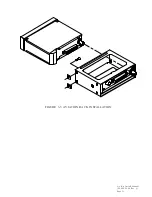
Page 21: ...Av Kit Install Manual 190 00026 00 Rev Q Page 21 FIGURE 3 5 AVIATION RACK INSTALLATION ...
Page 24: ...Av Kit Install Manual 190 00026 00 Rev Q Page 24 FIG A 1 FUNCTIONAL BLOCK DIAGRAM ...
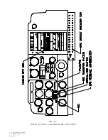
Page 26: ...Av Kit Install Manual 190 00026 00 Rev Q Page 26 FIG A 3 PANEL LAYOUT AND BREAKER LOCATION ...
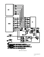
Page 27: ...Av Kit Install Manual 190 00026 00 Rev Q Page 27 FIG A 4 WIRING DIAGRAM ...
Page 30: ...Av Kit Install Manual 190 00026 00 Rev Q Page 30 ...