background image

Magnetic Heading Reference (continued)

To select a heading reference:

1. Highlight the ‘HEADING’ field and press 

F

.

2. Select the desired heading preference.

3. Press the 

F

key to confirm the selection.

To enter a user-defined magnetic heading

:

.

1. Select the ‘USER MAG’ option and press 

F

.

2. Use the 

U

and 

D

keys to enter the degrees 

and direction of magnetic variation.

3. Press the 

F

key to confirm the magnetic 

variation value.

Map Setup and Orientation

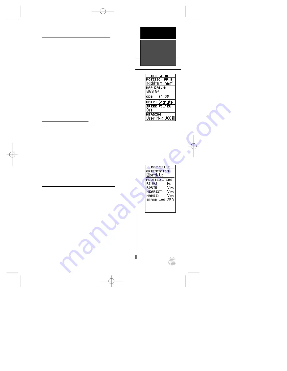
The map setup page lets you select map orientation

and specify what items are displayed. The map may be
oriented to north up, the direction of current travel
(track up) or the direction of an active route leg
(desired track up). The default setting is track up.

To change the map orientation:

1. Highlight the ‘ORIENTATION’ field and press 

F

.

2. Use the 

U

and 

D

keys to toggle through and

select the desired setting, and press 

F

.

Selecting Displayed Items on the Map Page

The rest of the map setup page lets you specify

what items are displayed or plotted on the Map Page.
The first four plot items may be turned on or off by
selecting ‘yes’ or ‘no’ in the appropriate field:

• The ‘RINGS’ selection will display the three pre-

sent position range rings on the map.

• The ‘ROUTE’ selection will plot the straight leg

lines between waypoints of an active route and
display all route waypoint names.

51

To enter a user-defined
magnetic variation, select
the ‘User Mag’ option and
enter the desired direction
and value.

REFERENCE

Magnetic

Heading & Map

Setup

The ‘North Up” orientation
causes the top-center of the
Map Page to represent
000º, the right-center to be
090º, the bottom-center
180º, and the left-center to
be 270º.

120XL Man RevB  7/10/98 10:55 AM  Page 51

Summary of Contents for GPS 120XL

Page 1: ...GPS 120XL Marine Navigator ZOOM O w n e r s M a n u a l R e f e r e n c e 120XL Man RevB 7 10 98 10 54 AM Page i...

Page 2: ...roduced or transmitted in any form or by any means electronic or manual including photocopying and recording for any purpose without the express written permission of GARMIN Information in this docume...

Page 3: ...section has been designed to acquaint you with the unit and provide a basic working knowl edge necessary to use the unit in typical conditions Reference provides detailed explanations of the advanced...

Page 4: ...essary FCC standards This equipment generates uses and can radiate radio frequency energy and if not installed and used in accor dance with the instructions may cause harmful interference to radio com...

Page 5: ...Using Waypoints 19 26 TracBack Navigation 27 28 Creating and Using Routes 29 34 Using the Compass and Highway Navigation Pages 35 37 Map Plotting Zooming and Cursor Movement 38 40 Menu Page and Distan...

Page 6: ...c data must be acquired before GPS navigation can begin Bearing The compass direction from your position to a destination Course Made Good CMG The bearing from the active from position your starting p...

Page 7: ...e that passes through the north and south poles Navigation The process of traveling from one place to another and knowing where you are in relation to your desired course Position An exact unique loca...

Page 8: ...nd navi gation information using degrees a measurement measured in a clockwise direction from a north reference North is described as 000 east as 090 south as 180 and west as 270 The diagram and compa...

Page 9: ...By using an almanac a timetable of satellite numbers and their orbits stored in the receiver s memory the GPS 120XL can determine the distance and position of any GPS satellite and then use this info...

Page 10: ...se This usually provides a position fix in a few minutes AutolocateTM allows the GPS 120XL to initialize itself and calculate a position fix without knowing your present position This usually provides...

Page 11: ...atellite signals to calculate a position Have you selected the right country state region from the EZinit list Check for the correct approximate lat lon on the Position Page or reselect the appropriat...

Page 12: ...ttom of the page contains a row of signal strength bars corresponding to each satellite being used Position Page The Position Page shows you where you are what direction you re heading and how fast yo...

Page 13: ...phic highway to show your movement in relation to your desired course The upper section shows bearing and distance to the waypoint and your current track and speed The middle portion contains the actu...

Page 14: ...may use the built in navigation simulator to practice using the GPS 120XL To use the simulator see page 54 Marking a Waypoint To begin the tour let s take the position you have acquired either by jus...

Page 15: ...waypoint named DOCK The mark position page will now be replaced by the Position Page or whatever page was displayed prior to pressing the M key The DOCK waypoint is now stored in the GPS 120XL s memo...

Page 16: ...of the screen The dark circle below the dia mond represents the position you created with the line between the two showing your track 1 Once you have reached an area that allows for gener al changes i...

Page 17: ...The Highway Page default will appear The GPS 120XL s Highway Page provides graphic steering guidance to a destination with an emphasis on a straight line course to the desired waypoint and the distanc...

Page 18: ...Compass Page see picture above left instead of the Highway Page To select the Compass Page 1 While viewing the Highway Page press F twice The Compass Page will now become the displayed navigation page...

Page 19: ...R LOG option The clear log confirmation page will appear 5 Use the L key to highlight the Yes prompt 6 Press F to finish Turning the Receiver Off You ve now gone through the basic operation of your ne...

Page 20: ...ing for a particular satel lite the corresponding signal strength bar will be blank and the sky view indicator will remain highlighted in reverse video Once the receiver has found the satellite a holl...

Page 21: ...GPS Coverage the receiver is no longer tracking enough satellites for a 2D or 3D fix Not Usable the receiver is unusable possibly due to incorrect initialization or abnormal satellite conditions Turn...

Page 22: ...e offset options are available from the sys tem setup menu see page 47 Trip Odometer The Position Page also features a resettable trip odometer to measure your total distance traveled To reset the tri...

Page 23: ...ult 3 digit waypoint name To change the default position name 1 Press the U key twice to move the field highlight from the save field to the name field 2 Press F to begin entry of the name Pressing th...

Page 24: ...an give you the closest points of safety in your area at a glance The nearest waypoints page will also let you retrieve a waypoint definition page or GOTO a selected way point right from the list To r...

Page 25: ...select a highlighted waypoint as a destination press the G key 3 Once the GOTO waypoint page appears press the F key to confirm the selected waypoint as your destination To delete all user defined way...

Page 26: ...e receiv er s last known position shown if one exists 4 Press F to begin entry of the position 5 Use the U and D keys to enter your position and use the L and R keys to move to each character field 6...

Page 27: ...the bearing and distance of your new waypoint from the reference waypoint Remember to use the F key to begin entry and confirm each field The coordinates will be calculated and saved for your new wayp...

Page 28: ...tion To change or add a comment 1 Use the U and D keys to highlight the comment field 2 Press F to begin entry of your comment 3 Enter the comment and press the F key to confirm Renaming and Deleting...

Page 29: ...the waypoint name field and press F 2 Press the L key to clear the name field 3 Use the U and D keys to scroll through way points 4 If you have more than one waypoint that begins with the same letter...

Page 30: ...To cancel an active GOTO 1 Press the G key 2 Use the arrow keypad to move the field highlight to the CANCEL GOTO prompt at the bottom of the page and press F Man Overboard Function The GPS 120XL s man...

Page 31: ...2 Press F to access the track log page 3 Use the U key to highlight the CLEAR LOG option 4 Press F A confirmation page will appear 5 Use L to highlight the Yes prompt and press F To activate a TracBa...

Page 32: ...TracBack route If the receiver is turned off or you lose satellite coverage during your trip the TracBack route will simply draw a straight line between any point where coverage was lost and where it...

Page 33: ...ller segments called legs The waypoint you are going to in a leg is called the active to waypoint and the way point immediately behind you is called the active from waypoint The line between the activ...

Page 34: ...istance of the route is indicated below the waypoint list The bottom of the route definition page features several function fields which let you copy clear invert or activate the displayed route Route...

Page 35: ...the active or TracBack route and want to save the route for future use To copy a route 1 Highlight the route number field and press F 2 Enter the route number to be copied and press F 3 Highlight the...

Page 36: ...iginal You will have to copy the active route to an unused storage route to save it since new route or TracBack activation overwrites route 0 To activate a route 1 Select the route definition page and...

Page 37: ...g or invert the active route without using the route definition page To invert a route from the active route page 1 Press the U key once to move the field highlight to the INVERT prompt 2 Press the F...

Page 38: ...overwritten by a new route activation If you add delete or change the first or last way point of a route the default comment first and last waypoint will automatically be updated On Route GOTOs At the...

Page 39: ...direction of travel The Compass Page is ideal for activities like trawling or entering a harbor and provides better steering guidance for slow speed e g walking travel with many directional changes Bo...

Page 40: ...navigate toward a waypoint the highway will actually move indicating the direction you re off course relative to the position diamond on the CDI scale To stay on course simply steer toward the center...

Page 41: ...rrow combine to show current direction and current destination at a glance The bottom of the Compass Page shows your current track TRK and speed SPD over the ground When you are one minute away from t...

Page 42: ...es 51 52 for more information The four corners of the Map Page are used to dis play various navigation data including the bearing and distance to a destination waypoint and your current track and spee...

Page 43: ...istance and bearing from your present position to the target crosshair will appear in the upper corners of the map If you are conducting a GOTO at the time you activate the panning function the crossh...

Page 44: ...er a new name and route number and press F You can also use the target crosshair as an instant GOTO destination This function will mark and instant ly set a course for a new waypoint called MAP To GOT...

Page 45: ...ghlight the to field and enter the destination way point Press the F key to calculate the range and bearing to the destination waypoint 3 Highlight the date field and enter the date for your destinati...

Page 46: ...ERIA field and press F 2 Use U or D to select Time Interval and press F 3 Press F to begin entry of the interval 4 Enter a value in hours minutes and seconds and press the F key Managing and Clearing...

Page 47: ...d select the desired setting and press F The GRMN GRMN setting is a proprietary format that lets you exchange information such as waypoints routes and track logs between two GARMIN GPS devices or a PC...

Page 48: ...ss of errors induced by the U S government s Selective Availability SA program The RTCM NONE format will allow connection to any manually tuned beacon receiver by using the proper output interface The...

Page 49: ...on signal is being tuned Once the beacon signal has been tuned a Receiving message will be displayed If a beacon signal is tuned and no corrections are being received a No Data message will be dis pla...

Page 50: ...Date and Time Setup The date and time field is located directly below the mode field Because the time shown is UTC time you will need to enter a time offset to display the correct local time for your...

Page 51: ...ighlight to the CONTRAST field and press the F key 2 Use the L and R keys to adjust the bar scale for the desired contrast and press the F key Tone Setting You may choose from three settings for audib...

Page 52: ...ting by pressing F Map Datums The map datum field is located just below the posi tion format field and comes with a WGS 84 default set ting Although 104 total map datums are available for use see the...

Page 53: ...he GPS 120XL lets you select nautical default statute or metric units of measure for all speed and dis tance fields To change the unit of measure 1 Highlight the units field and press the F key 2 Use...

Page 54: ...lue field and press the F key 4 Use U and D to select the desired number of seconds 5 Press the F key to confirm the selection Magnetic Heading Reference The GPS 120XL s heading information can be dis...

Page 55: ...hlight the ORIENTATION field and press F 2 Use the U and D keys to toggle through and select the desired setting and press F Selecting Displayed Items on the Map Page The rest of the map setup page le...

Page 56: ...ter The maximum setting is 768 points Once the maximum number of track points is reached the older points will be lost as new points are added Note that adjusting the points displayed will not affect...

Page 57: ...9 99 distance units To set the alarms 1 Move the highlight to ALARMS SETUP and press F 2 Select the desired alarm distance field and press F 3 Enter the distance for the alarm and press F 4 If you wou...

Page 58: ...Highway Page to set your speed and track You may also enter a new position if you desire only from the Position Page To enter track speed and position 1 Highlight the TRACK field and press the F key...

Page 59: ...rst then the unit and wiring harness Mounting the GPS antenna The antenna should be mounted in a location that has a clear unobstructed view of the sky in all direc tions to ensure the best reception...

Page 60: ...data cables The mounting surface should be rigid enough to support the unit and protect it from excessive vibration and shock To surface mount the GPS 120XL 1 Place the mounting bracket in the desired...

Page 61: ...s against the mounting surface 3 From the back side of the panel loosely attach the bracket such that the slot in the ratchet area points away from the mounting panel 4 Rotate the bracket downward unt...

Page 62: ...te harness connections To connect the GPS 120XL to a power source 1 Connect the RED harness lead to the positive side of a 10 40 volt DC power source Make sure the power lead has an in line 1 amp fuse...

Page 63: ...on to 3g s POWER Input 10 40v DC Usage 2 watts Specifications subject to change without notice With optional GARMIN GBR 21 Beacon Receiver Input Subject to accuracy degradation to 100m 2DRMS under the...

Page 64: ...able Take your unit to an authorized GARMIN dealer for repairs Received an Invalid WPT A waypoint was received during upload transfer that has an invalid identifier Receiver has Failed A failure in r...

Page 65: ...t exist in the database and has been deleted from the route RTCM Input has Failed DGPS data being received has been lost You are no longer receiving the beacon signal Searching the Sky The GPS 120XL i...

Page 66: ...Australian Geod 66 Australia Tasmania Island Astrln Geod 84 Australian Geod 84 Australia Tasmania Island Bellevue IGN Efate and Erromango Islands Bermuda 1957 Bermuda 1957 Bermuda Islands Bogata Obse...

Page 67: ...on Mindanao Island Luzon Philippine Luzon Philippines excluding Mindanao Island Mahe 1971 Mahe 1971 Mahe Island Marco Astro Marco Astro Salvage Island Massawa Massawa Eritrea Ethiopia Merchich Merchic...

Page 68: ...Reunion Mascarene Island Rome 1940 Rome 1940 Sardinia Island RT 90 Sweden Santo Dos Santo Dos Espirito Santo Island Sao Braz Sao Braz Sao Miguel Santa Maria Islands Azores Sapper Hill 43 Sapper Hill...

Page 69: ...Routes 33 Estimated Time Enroute ETE 2 Estimated Time of Arrival ETA 2 G GPS Antenna 55 Getting Started Tour 10 Glossary 2 Going To a Waypoint GOTO 13 Grid 3 Ground Speed 3 H Highway Page 36 I Index 6...

Page 70: ...Speed Filter 49 System Setup 46 T Table of Contents 1 Time Format 47 Tone Setting 47 TracBack 27 43 TracBack Tips 28 Track TRK 3 Track Criteria 42 Track Log Display 52 Track Log Setup Page 42 Trip Odo...

Page 71: ...ntained herein are exclusive and in lieu of all other warranties expressed or implied including any lia bility arising under warranty of merchantability or fitness for a par ticular purpose statutory...

Page 72: ...Corporation 1200 E 151st Street Olathe KS USA 66062 GARMIN Europe Ltd Unit 5 The Quadrangle Abbey Park Romsey UK SO51 9AQ Part Number 190 00136 00 Rev B Printed in Taiwan 120XL Man RevB 7 10 98 10 55...

Reviews: