Garmin GNC 420W Quick Reference Download Page 8

6

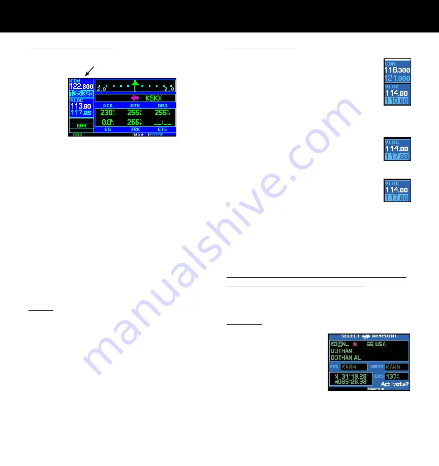
Screen Layout (windows)

COM 

Window

GPS 

Window

Active Frequency on top & Standby on bottom  

(active window highlighted by cursor)

{
{

VLOC 

Window

{

The 400W-series display is divided into four separate 

“windows” (or screen areas). The top left 1/4 of the display 
provides a COM window (top two lines) and a VLOC 
window (bottom two lines) The three lines at the bottom 
left of the display are used for terrain, flight phase, and 
GPS integrity annunciators. The right 3/4 of the display 
consists of a GPS window, which is where you’ll find the 
various navigation, waypoint information and settings 
“pages.” 

Each unique screen of information is referred to as 

a page. Pages are typically selected using the 

small

 and 

large right 

knobs—with the cursor removed from the 

GPS window. See the following page for details on arrange-
ment of the 400W-series main pages. 

Cursors

There are two separate cursors: a tuning cursor and a 

GPS window cursor. The tuning cursor is used to select 
the standby COM or VLOC frequency. If desired, press the 

small left 

knob to move the tuning cursor to the VLOC 

window. Then, use the 

small

 and 

large left 

knobs to 

select the desired frequency. The 

COM

 and 

VLOC flip-

flop 

keys are used to swap the active and standby frequen-

cies. Push in on 

small right

 knob and then turn the 

large 

right 

knob to move the GPS window cursor around the 

page. 

Frequency Selection

1.   If the tuning cursor is not currently in 

the  desired  window  (COM  or VLOC), 

press the 

small left 

knob momentarily 

to  switch  the  highlight  between  the 

COM and VLOC windows. Adjusting the 

frequencies with the 

large

 and 

small 

left

 knobs will affect the standby fre-

quency. 

2.   Turn  the 

large  left 

knob  to  select 

the  desired  megahertz  (MHz)  value. 
For example, the “117” portion of the 
frequency “117.80”. 

3.   Turn the 

small left 

knob


to select the 

desired kilohertz (kHz) value. For exam-
ple, the “.80” portion of the frequency 
“117.80”. 

4.   To  activate  the  selected  frequency,  press  the 

appropriate 

flip-flop 

key  to  swap  the  COM  or 

VLOC frequency  from the standby into the active 
window. 

To Quickly Tune and Activate the 121.500 Emergency 

Channel (GNS 430W and GNC 420W only)

1.   Press and hold the 

COM flip/flop 

key for approxi-

mately two seconds. 

Data Entry

Data is entered in the GPS 

window using the 

large

 and 

small right 

knobs. The 

large 

right 

knob is used to move 

the cursor between fields. The 

small right 

knob is used to 

select individual characters at 
the highlighted cursor location. 

SCREEN LAYOUT/CURSORS/FREQ SELECTION/DATA ENTRY

Summary of Contents for GNC 420W

Page 1: ...400W Series Quick Reference ...

Page 2: ...q Flip Flop Nav Radio Volume Small Knob Com VLOC Freq kHz Com Freq Window Small Knob Cursor Press to activate Large Knob Aviation Database Card Flight Plan Key Cam Lock Message Key CDI Key Navigation Source GPS VLOC or GPS PTK Nav Freq Window Large Knob Com VLOC Freq MHz Terrain Flight Phase and GPS Integrity Annunciator Terrain Database Card Waypoint and arrival alerts turn advisories function an...

Page 3: ...oved navigation charts Pilots will enjoy the GPS 400W as a multi function display MFD especially when it is coupled with traf fic lightning detection and weather interfaces like Ryan TCAD TIS from the Garmin GTX 330 Mode S transpon der L3 SKYWATCH or STORMSCOPE WX 500 With the FDE prediction program included with the Trainer CD the GPS 400W may be used for oceanic or remote opera tions For the late...

Page 4: ...rently selected by the tuning cursor v In the GNC 420W and GNS 430W the small left knob is used to tune the kilohertz kHz value of the standby frequency for the COM transceiver or the VLOC receiver whichever is currently selected by the tuning cursor Press this knob momentarily to toggle the tuning cursor between the COM and VLOC windows W In the GNC 420W and GNS 430W the COM flip flop key is used t...

Page 5: ...nd hold this key to immediately display the Default NAV Page E The enter key ENT is used to approve an operation or complete data entry It is also used to confirm information such as during power on t The large right knob is used to select between the various page groups NAV WPT AUX or NRST With the on screen cursor enabled the large right knob allows you to move the cursor about the page r The sma...

Page 6: ...encing to the next waypoint Press ing the OBS key again returns to normal operation with automatic sequencing of waypoints Whenever OBS mode is selected you may set the desired course to from a waypoint using the OBS Page or an external OBS selector on your HSI or CDI M The message MSG key is used to view system messages important warnings and requirements F The flight plan FPL key allows you to cr...

Page 7: ...l self test page There may be more self test screens depending on optional equipment installed in your aircraft 4 The instrument panel self test page allows you to verify that the unit is communicating properly with in panel instruments Compare on screen indications with the information depicted on connected instruments such as the CDI HSI RMI and or external annunciators Once you have veri fied pr...

Page 8: ...d frequency The COM and VLOC flip flop keys are used to swap the active and standby frequen cies Push in on small right knob and then turn the large right knob to move the GPS window cursor around the page Frequency Selection 1 If the tuning cursor is not currently in the desired window COM or VLOC press the small left knob momentarily to switch the highlight between the COM andVLOC windows Adjustin...

Page 9: ...key and using the small right knob to select the desired page FPL Group Active Flight Plan Flight Plan Catalog Procedures PROC Small right knob to select pages within the group Large right knob to change page groups Five or more NAV pages are available when the unit s installation includes connection to traffic and or weather information sources Default NAV Map NAVCOM Position Terrain Satellite Sta...

Page 10: ...the Change Fields option and press the ENT key to select this option 3 Use the large right knob to highlight the data field you wish to change 4 Turn the small right knob to display the list of available data items Continue turning the small right knob to select the desired data item from the list 5 Press the ENT key to select the desired data item and return to the default NAV page 6 Press the sma...

Page 11: ...e 2 Press the CLR key as needed to select the desired amount of map detail To Turn the Data Fields On Off on the Right Side of the Map 1 With the map page displayed press MENU to display an options menu 2 Turn the large right knob to highlight Data Fields Off and press the ENT key 3 To re display the data fields follow steps 1 and 2 but instead select Data Fields On from the options menu To Select ...

Page 12: ...rolling through the list of frequencies as described in the previous procedure 2 To place a frequency in the standby field of the COM or VLOC window highlight the desired frequency and press the ENT key Terrain Page To display the TERRAIN Page select the NAV group and turn the small right knob until the TERRAIN Page is displayed The page displays terrain information aircraft ground track and GPS de...

Page 13: ...ion of the desired destination waypoint As you spell the facility name or city the 400W series Spell N Find feature will select the first entry in the database based upon the characters you have entered up to that point 5 Once the name is entered the information for that airport will appear on the page Press ENT to accept the selected identifier 6 To view the other airport information pages press th...

Page 14: ...age will appear with the waypoint identifier field highlighted 2 Turn the large right knob to highlight the facility name second line or the city third line field 3 Use the small and large right knobs to enter the facility name or city location of the desired destination waypoint As you spell the facility name or city the 400W series Spell N Find feature will select the first entry in the database bas...

Page 15: ...e which part of the list is currently being viewed 3 To remove the flashing cursor press the small right knob To View Additional Information for a Nearby Airport 1 Highlight the identifier of the desired airport by scrolling through the list as described in the pro cedure above 2 Press ENT to display the airport location page for the selected airport 3 To view additional WPT pages for the selected a...

Page 16: ...an and press the ENT key To Stop Navigating a Flight Plan 1 Press the FPL key 2 Press the MENU key to display the active flight plan options 3 Turn the large right knob to highlight Delete Flight Plan and press the ENT key Press the ENT key again to con firm To Edit a Flight Plan 1 Press the FPL key and turn the small right knob to display the Flight Plan Catalog 2 Press the small right knob to acti...

Page 17: ...PS guidance on such approaches is strictly for monitoring only use the VLOC receiver and external CDI or HSI for primary navigation To confirm this reminder highlight Yes and press the ENT key Not all approaches in the database are approved for GPS use As you select an approach a GPS designa tion to the right of the procedure name indicates the procedure can be flown using the GPS receiver Some proc...

Page 18: ...ect Approach option from the procedures page Otherwise you must first choose the airport then the approach procedure When a localizer based approach such as an ILS is loaded the desired frequency is automatically placed in standby on the VLOC window To activate the frequency press the VLOC flip flop key If the VLOC receiver will be used for the approach be sure to switch the external CDI or HSI to VL...

Page 19: ...ain to return to automatic waypoint sequencing For course reversals waypoint sequencing is suspended for one trip around the holding pattern only after which it will return to automatic waypoint sequencing The CDI will guide you through a DME arc Just keep the needle centered as you fly along the arc As you cross the missed approach point SUSP will appear above the OBS key indicating that automatic...

Page 20: ...ch such as ILS or Localizer MAPR Missed Approach indicates the system is providing missed approach integrity and CDI full scale deflection 0 3 NM This also shows that the pilot has initiated a Missed Approach by pressing the OBS key after crossing the MAP ENR En route CDI full scale deflection is 2 0 NM or current CDI scale selection whichever is smaller TERM Terminal CDI full scale deflection is 1 0...

Page 21: ......

Page 22: ... Kansas 66062 U S A Garmin AT Inc 2345 Turner Rd S E Salem Oregon 97302 U S A GARMIN Europe Ltd Unit 5 The Quadrangle Abbey Park Industrial Estate Romsey SO51 9AQ U K GARMIN Corporation No 68 Jangshu 2nd Road Shijr Taipei County Taiwan www garmin com Part Number 190 00356 01 Rev A ...

Reviews: