


400 SERIES INSTALLATION MANUAL
Page F-1
190-00140-02
Rev.
Q
Appendix F. DRAWINGS AND INTERCONNECTS
F.1 INTRODUCTION
This section contains installation drawings to aid in the installation of a 400 series unit.
Additional information and notes included on the drawings can be used as reference information
during installation.
F.2 DRAWING
LIST
The following drawings are included in this section:
Figure F-1—GA 56 Antenna Installation Drawing
Figure F-2—GNS 430 Mounting Rack Dimensions
Figure F-3—GNC 420 Mounting Rack Dimensions
Figure F-4—GPS 400 Mounting Rack Dimensions
Figure F-5—GNS 430 Mounting Rack Installation
Figure F-6—GNC 420 Mounting Rack Installation
Figure F-7—GPS 400 Mounting Rack Installation
Figure F-8—400 Series Recommended Panel Cutout Dimensions
Figure F-9—400 Series System Interface Diagram
Figure F-10—GNS 430 Typical Installation
Figure F-11—GNC 420 Typical Installation
Figure F-12—GPS 400 Typical Installation
Figure F-13—Power, Lighting, and Antenna Interconnect
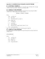
Figure F-14—Altimeter Interconnect
Figure F-15—Main Indicator Interconnect
Figure F-16—KI 209A Main Indicator Interconnect
Figure F-17—KI 208A Main Indicator Interconnect
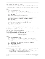
Figure F-18—Annunciators/Switches Interconnect
Figure F-19—RS-232 Serial Data Interconnect
Figure F-20—ARINC 429 EFIS Interconnect
Figure F-21—ARINC 429 Sandel EHSI Interconnect (1 400 Series Unit, I Sandel SN3308)
Figure F-22—ARINC 429 Sandel EHSI Interconnect (2 GNS 430, 1 Sandel SN3308)
Figure F-23—ARINC 429 Sandel EHSI Interconnect (2 GNS 430, 2 Sandel SN3308)
Figure F-24—ARINC 429/RS 232 Air Data/IRU/AHRS Interconnect
Figure F-25—ARINC 429 Flight Control Interconnect
Figure F-26—Traffic Advisory System Interconnect
Figure F-27—Weather and Terrain Interconnect
Figure F-28—Audio Panel Interconnect
Summary of Contents for GNC 420
Page 8: ...Page vi 400 SERIES INSTALLATION MANUAL Rev Q 190 00140 02 This page intentionally left blank ...
Page 28: ...Page 3 8 400 SERIES INSTALLATION MANUAL Rev Q 190 00140 02 This page intentionally left blank ...
Page 78: ...Page A 8 400 SERIES INSTALLATION MANUAL Rev Q 190 00140 02 This page intentionally left blank ...
Page 80: ...Page B 2 400 SERIES INSTALLATION MANUAL Rev Q 190 00140 02 ...
Page 81: ...400 SERIES INSTALLATION MANUAL Page B 3 190 00140 02 Rev Q ...
Page 82: ...Page B 4 400 SERIES INSTALLATION MANUAL Rev Q 190 00140 02 ...
Page 83: ...400 SERIES INSTALLATION MANUAL Page B 5 190 00140 02 Rev Q ...
Page 84: ...Page B 6 400 SERIES INSTALLATION MANUAL Rev Q 190 00140 02 ...
Page 85: ...400 SERIES INSTALLATION MANUAL Page B 7 190 00140 02 Rev Q ...
Page 86: ...Page B 8 400 SERIES INSTALLATION MANUAL Rev Q 190 00140 02 ...
Page 87: ...400 SERIES INSTALLATION MANUAL Page B 9 190 00140 02 Rev Q ...