background image

190-02488-01 Rev. B

Pilot’s Guide

1-17

System at a Glance

Compatible Equipment

Line Replaceable Units

ADC & AHRS

AHRS units have a magnetometer interface for determining magnetic heading. 
ADC units have a Pitot-static interface for measuring pressure altitude.

LRU

DISPLAY

FUNCTION

GDC 74

ADC

GNX

Air temperature

Pressure Altitude

G3X

G500/G600

GPS

GNC
GNX

ADC

Air temperature

Pressure Altitude

AHRS

Heading

GSU 25/73

Integrated ADAHRS

GNX

GRS 77

AHRS

GNX

Heading

SYSTEM REQUIRED LRUS

GPS antenna

SYSTEM OPTIONAL LRUS

ADAHRS or ADC with AHRS

Audio panel

GAD 29 adapter

GAE 12 altitude encoder

(GNX 375 only)

G3X Touch

G500/G600

G500/G600 TXi

GMX 200

MX 20

OPTIONAL INTERFACES

GDL 88/GTX 345 ADS-B transceiver 

(GPS 175 & GNC 355 only)

The system consists of multiple LRUs, 
which are installed behind the 
instrument panel or in a separate 
avionics bay. Their modular design 
aids system maintenance and unit 
replacement. 

Optional LRUs may include 
compatible equipment from either 
Garmin or a third party 
manufacturer.

Summary of Contents for GNC 355

Page 1: ...GPS 175 GNC 355 GNX 375 Pilot s Guide...

Page 2: ...are registered trademarks of Garmin International or its subsidiaries Connext Garmin Pilot G3X Touch and Smart Airspace are trademarks of Garmin International or its subsidiaries These trademarks may...

Page 3: ...Units 1 17 ADC AHRS 1 17 Altitude Encoder 1 18 2 GET STARTED 2 1 Power Up 2 2 Instrument Test 2 2 Power Off 2 2 Databases 2 3 Database Effective Cycles 2 4 Active and Standby Databases 2 5 Manual Upda...

Page 4: ...quawk Code Keys 2 40 VFR 2 40 XPDR Key 2 40 Remote Control 2 42 XPDR Alert 2 42 ADS B Altitude Reporting 2 43 ADS B Control Panel 2 43 ADS B Key 2 44 Enabling Anonymous Mode 2 44 Assigning a Flight ID...

Page 5: ...PO Scale 3 10 Range Ring 3 10 Track Vector 3 11 Ahead View 3 11 Map Detail 3 12 Map Interactions 3 14 Basic Interactions 3 14 Graphical Flight Plan Editing 3 16 Map Overlays 3 20 Overlay Controls 3 20...

Page 6: ...s 3 67 Departures 3 69 Flight Plan Departure Options 3 70 Arrivals 3 71 Flight Plan Arrival Options 3 72 Approaches 3 73 Flight Plan Approach Options 3 75 Missed Approach 3 76 Approach Hold 3 77 DME A...

Page 7: ...nds Temps Aloft 5 18 Icing 5 18 Turbulence 5 19 TFRs 5 19 Raw Text Reports 5 20 FIS B Ground Reception Status 5 22 Traffic Awareness 5 23 Traffic Applications 5 23 Traffic Application Failures 5 24 Tr...

Page 8: ...6 8 Pilot Specified Advisories 6 9 System Hardware Advisories 6 10 COM Radio Advisories GNC 355 6 14 Terrain Advisories 6 15 Traffic System Advisories 6 16 Traffic Advisories GPS 175 GNC 355 6 16 Tra...

Page 9: ...er use GPS altitude for vertical navigation The altitude calculated by GPS receivers is geometric height above Mean Sea Level and could vary significantly from the altitude displayed by pressure altim...

Page 10: ...tacle and terrain avoidance information WARNING Do not use GPS to navigate to any active waypoint identified as a NON WGS84 WPT by a system message NON WGS84 WPT waypoints are derived from an unknown...

Page 11: ...ld void both the warranty and affect the airworthiness of the aircraft NOTE The application supports channel tuning for both 8 33 kHz and 25 kHz channels within radio frequency range If flying in a re...

Page 12: ...notice is being provided in accordance with California s Proposition 65 If you have any questions or would like additional information please refer to our website at www garmin com prop65 NOTE Operati...

Page 13: ...ipment NOTE The pilot operator must review and be familiar with Garmin s database exclusion list as discussed in SAIB CE 14 04 to determine what data may be incomplete The database exclusion list can...

Page 14: ...ning to Map Menu in section Map Setup 3 20 Added Lightning to Overlay Selections in section Map Overlays 3 21 Added Lightning functionality to Overlay Controls 3 54 Added section FastFind Predictive W...

Page 15: ...t the information pertains to both products When you see a product name in bold e g GNC 355A it means that the information pertains to that specific model only GPS 175 GNC 355 GNC 355A GNX 375 Unless...

Page 16: ...One ADS B Transponder Pilot s Guide 190 01499 00 WEBSITE ADDRESS Aviation Limited Warranty https www garmin com en US legal aviation limited warranty Database Concierge Go to http www flygarmin com s...

Page 17: ...190 02488 01 Rev B Pilot s Guide 1 1 System at a Glance 1 System at a Glance OVERVIEW 1 2 PILOT INTERFACE 1 5 COMPATIBLE EQUIPMENT 1 17...

Page 18: ...he GNC 355 supports 25 kHz channel spacing while the GNC 355A provides tuning for both 25 kHz and 8 33 khz channels Both GPS 175 and GNC 355 can receive ADS B In weather and traffic when interfaced to...

Page 19: ...t s Guide 1 3 System at a Glance Unit Configurations COMPARISON TABLE Unit GPS MFD COM Radio Mode S XPDR Dual link ADS B In 1090 ES ADS B Out GPS 175 GNC 355 GNX 375 GPS 175 GPS MFD GNX 375 GNC 355 GP...

Page 20: ...rnal GPS Receiver Built in Bluetooth Antenna Database Concierge Access 4 Moving Map Terrain Flight Plan Graphical Flight Planning Waypoint Information Nearest FastFind Predictive Waypoint Entry FIS B...

Page 21: ...easures cockpit ambient light level to automatically adjust display brightness for day and night 4 SD Card Slot Interface for loading database exporting log files and updating software Compatibility w...

Page 22: ...s an SD card for the following tasks INSERT AN SD CARD When inserting an SD card 1 Verify unit power is off and the slot is empty 2 Hold card such that label faces left edge of display screen 3 Ensure...

Page 23: ...w keys Increasing decreasing values continuously SWIPE A smooth motion that involves touching an object then sliding your finger across the screen and lifting up Use this gesture for Accessing multipl...

Page 24: ...subpages e g Utilities System Open the system messages list A flashing icon indicates unread messages Cancel an active function without inputting data Open a context menu Input a specified value Retu...

Page 25: ...ys related to a single function e g FIS B Weather When scrolling all keys in the list are inactive An indicator at the bottom of the menu shows which pane is active Active Pane Multiple panes are acce...

Page 26: ...he navigator employs multiple keypad types to serve specific settings and functions NUMERIC ALPHANUMERIC Alphanumeric keypads comprise multiple keysets that are accessible by way of swipe or key selec...

Page 27: ...ome page GNC 355 355A Outer Knob Selecting a page shortcut Cursor placement and initial field page selections Moving cursor forward or backward within data field Tuning major frequency digits Adjustin...

Page 28: ...e but are not limited to the following GPS 175 GNX 375 Slot 1 Slot 3 Slot 2 Active Page Slot 1 is a dedicated Map shortcut Slots 2 and 3 are customizable Selectable page options are dependent upon con...

Page 29: ...ng once opens the Direct To window After a waypoint fix is selected pushing the knob again activates the direct to fix Map Active Flight Plan Active Available functions Map zoom Set knob focus to stan...

Page 30: ...e the standby frequency Pushing twice sets the knob focus to the volume slider Turn the inner and outer knobs to adjust the volume percentage Pushing again closes the menu and returns to the previous...

Page 31: ...es to an SD card at any time using a screen capture Images automatically save to the print folder in the SD card root directory A camera icon momentarily shows in the annunciator bar indicating a succ...

Page 32: ...y conditions Green Safe operating conditions Engaged modes Active COM frequency White Scales and markings Current data and values Heading legs Magenta GPS data Active flight plan legs Parallel track C...

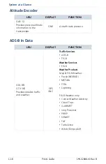
Page 33: ...ng GSU 25 73 Integrated ADAHRS GNX GRS 77 AHRS GNX Heading SYSTEM REQUIRED LRUS GPS antenna SYSTEM OPTIONAL LRUS ADAHRS or ADC with AHRS Audio panel GAD 29 adapter GAE 12 altitude encoder GNX 375 only...

Page 34: ...sponder GNX Aircraft static pressure LRU DISPLAY FUNCTION GDL 88 GTX 345 Provides datalink traffic and weather GPS GNC Traffic Services ADS B TIS B Weather Services FIS B Weather Products Map FIS B We...

Page 35: ...2488 01 Rev B Pilot s Guide 2 1 Get Started 2 Get Started POWER UP 2 2 DATABASES 2 3 CONNECTIVITY 2 14 COM 2 18 XPDR 2 36 ADS B ALTITUDE REPORTING 2 43 PILOT SETTINGS 2 46 STATUS INDICATIONS 2 56 LOGS...

Page 36: ...operation continuous built in test features exercise the unit s processor memory external inputs and outputs The Instrument Test page displays the results of all external equipment checks performed by...

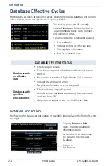
Page 37: ...om a Flight Stream 510 wireless datacard This method requires the Garmin Pilot app on a portable electronic device SUPPORTED DATABASES Basemap Bodies of water geopolitical boundary and road informatio...

Page 38: ...510 is present Includes Basemap and Terrain No pilot confirmation or restart required Databases with specified effective dates Effective during a specific period Unit determines database status using...

Page 39: ...Status Select Active or Standby VIEW COPYRIGHTS DB INFO PAGE DISPLAYS Active Information about databases currently in use View Copyrights key Standby Information about databases that are not yet effe...

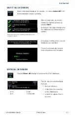
Page 40: ...is active i e during power up Database Updates Page DATABASE SOURCE INDICATION No indication means the database is either from an SD card or the unit s internal standby queue This page presents a lis...

Page 41: ...default this page displays only the databases recommended for update Basemap and Terrain update automatically and require no action A message notifies when no such databases are available The unit aut...

Page 42: ...use of a database error tap Error Info An information window provides details regarding the state of the database This key appears when two databases are of the same type and cycle but pertain to diff...

Page 43: ...ire pilot confirmation or a unit restart Automatic updates occur when A newer database is detected on the SD card or in the internal standby queue A newer database is within its effective dates The ai...

Page 44: ...on screen prompts Database Concierge Transfer Function Provides automatic updates for databases with effective dates Preloads databases that are not yet effective by placing them in the internal stan...

Page 45: ...o databases are available Database Concierge transfers databases from the app to Flight Stream 510 A progress bar shows when this process is complete Database Transfer Status The unit either updates o...

Page 46: ...rovided keypads 4 Enable Wi Fi setting on the portable device Wi Fi status changes to Open App once pairing is complete Flight Stream 510 requires power up Wi Fi is active but the unit is waiting to c...

Page 47: ...ndby database becomes effective each LRU automatically generates an update prompt Database SYNC Compatibility The Database SYNC function enables automatic database synchronization across all capable G...

Page 48: ...nsponder and ADS B 1 ADS B In traffic data 2 FIS B weather and flight information 2 AHRS data from built in sensor 3 4 1 GNX 375 only 2 GNX 375 or GPS 175 and GNC 355 with external ADS B In source 3 A...

Page 49: ...ing with up to 13 portable electronic devices via the Garmin Pilot app Bluetooth device management options reside on the Devices page Opening this page automatically initiates device pairing Device in...

Page 50: ...unit This action requires pilot confirmation Be sure to remove pairing on both devices before attempting to pair them again CONNECTION STATUS To view a list of all paired devices and their connection...

Page 51: ...tooth wireless technology It may be necessary to turn this function off if a portable device application makes repeated erroneous attempts to send flight plans to the unit Once transfer is complete an...

Page 52: ...Access Key 3 Frequency Entry Field 7 Data Entry Keys 4 Monitor Key VHF COM transceiver controls are accessible via the selectable standby STBY frequency window This control resides in the upper right...

Page 53: ...lume Relative Volume Indicator Knob Control Indicator Access volume controls by tapping the VOL indicator key on the COM Standby control panel or using the control knob as described below For convenie...

Page 54: ...hen listening to a distant station or setting the volume level Tap once to override the automatic squelch function Tap again to return the squelch to automatic operation SQ annunciates in the COM acti...

Page 55: ...r COM radio selections swipe to the end of the menu Setup options for GNC 355A shown as typical 8 33 kHz 25 kHz Channel Spacing Link to COM VOL Set offset value Sidetone Volume Reverse Frequency Looku...

Page 56: ...lying in a region where 8 33 kHz channel spacing is available set the COM radio to 8 33 kHz to prevent the loss of any stored or recently used frequencies Tapping this key toggles the transceiver chan...

Page 57: ...rifies the displayed frequency against the database at least once per minute Frequency Type Facility Identifier denotes more than one type associated with the frequency When frequency look up is activ...

Page 58: ...crophone that is played back in real time over the headset The offset setting determines sidetone volume for the COM during radio transmission Adjustments determine the amount that the sidetone volume...

Page 59: ...equency information sample text Communication frequencies are split between two selectable windows The upper window presents the active COM radio frequency This is the frequency currently in use for t...

Page 60: ...ndby frequency value displays in the direct tuning field Enter a new standby frequency using the provided data entry keys or by turning and pushing the control knob To cancel the entry and exit the co...

Page 61: ...ing field allows you the option of entering frequencies without typing the leading and or trailing digits For example To enter frequency 121 50 you need only tap 2 1 and 5 The field autofills the lead...

Page 62: ...h the standby frequency displayed in the lower window Tap once to swap the displayed frequency values Tap again to swap them back A transfer icon indicates that flip flop functionality is available Ta...

Page 63: ...ten to the standby frequency while the unit continues monitoring the active COM channel When the COM active frequency receives a signal the unit automatically switches back to the active frequency Onc...

Page 64: ...ports within a 200 nm radius Nearest FSS ARTCC List the distance bearing and frequency associated with the specified facility name Recent Lists up to 20 of the most recently tuned frequencies Flight P...

Page 65: ...ion about the associated waypoint Waypoint Identifier Bearing Distance Frequency Key This key appears when more than one frequency is available at the indicated identifier Applicable to functions disp...

Page 66: ...wn Selections do not activate until transfered to active Emergency Frequency This function provides a quick method for remotely tuning the emergency frequency 121 50 MHz This feature is available any...

Page 67: ...quencies Name Assign the frequency a unique identifier Frequency Specify a frequency value Save Add the frequency to the user frequency list Delete Remove the selected user frequency from the list App...

Page 68: ...d value 4 Tap Save EDIT USER FREQUENCY A pop up message informs when the user frequency list is full Tapping the Edit key for an existing entry opens the same pop up From here you may modify the user...

Page 69: ...uous broadcasting This may occur when Push to talk key on the microphone is stuck or accidentally left in the keyed position Push to talk function continues to transmit after releasing the key The adv...

Page 70: ...4 Squawk Code Entry Keys 2 VFR Key 5 Data Field 3 XPDR Mode Key Transponder controls are accessible via the XPDR key This key is unavailable when the control panel is active 5 4 2 1 3 The XPDR key be...

Page 71: ...nu to access the transponder setup options From here you can Change the display of data Enable 1090 ES ADS B Out functionality if configured Assign a unique flight ID Toggles the data field between pr...

Page 72: ...TIONS Availability dependent on configuration Flight IDs are alphanumeric upper case only and have an eight character limit The active flight ID displays by default Tapping ADS B Out allows the transm...

Page 73: ...nsponder is responding Transmitted ADS B Out does not include pressure altitude Altitude Reporting Transponder replies to identification and altitude interrogations Reply R symbol indicates the transp...

Page 74: ...r as underscores Activate the new code by tapping Enter To cancel the code entry and exit the page tap Cancel Active squawk codes remain in use until a new code is entered Tapping this key once sets t...

Page 75: ...IDENT function code unmodified Tap to accept modified code and initiate IDENT function IDENT Standby Mode Reply active IDENT function active No change to transponder code Standby mode Current squawk c...

Page 76: ...re designed to be immediately recognizable If a failure occurs while the control page is active the display automatically returns to the previous page Squawk code Transponder mode IDENT ADS B transmis...

Page 77: ...On GPS 175 it resides in the upper right corner of the display On GNC 355 it resides on the GDL 88 Status page 1 2 3 GDL 88 Features Remote mount ADS B transceiver Transmits ADS B Out messages to ATC...

Page 78: ...ion Instead of a flight ID the unit transmits the call sign VFR Squawk Code as reported by GDL 88 Transponder Mode ALT Active Transponder Depending on the configuration of your GDL 88 tapping the ADS...

Page 79: ...tely recognizable If a failure occurs while the control page is active the display automatically returns to the previous page UNIT CONDITION GPS 175 GNC 355 GDL 88 failure For information regarding pi...

Page 80: ...tomization options allow you to Set and display the CDI Specify runway criteria Set the date and time Specify COM radio settings 1 Create shortcuts Set the display units Adjust display brightness Othe...

Page 81: ...fix Scaling tightens from 1 0 nm to the angular full scale deflection defined for the approach typically 2 0 Horizontal Alarm Limits Horizontal alarm limits HAL are used to compare against GPS positio...

Page 82: ...or displays below the GPS NAV Status Indicator key CDI OFF CDI ON Only the Flight Plan page access key is available The CDI provides no indications without an active flight plan Lateral Deviation Indi...

Page 83: ...of any length to appear in the nearest airport list and be considered for use by Terrain Specify runway criteria from the System Setup app Selections determine which airports are suitable when using...

Page 84: ...play key Utilities Clock Timers Home Clock Generic Timer Trip Departure Timers Stopwatch style counter Count up or count down Specify countdown time using the preset function Measure elapsed airborne...

Page 85: ...r the Map page Tap a slot key and assign a page to that slot Page Shortcut Options Traffic Terrain Weather Nearest Airport Flight Plan Depending on configuration Traffic and Weather shortcuts may not...

Page 86: ...select which airspace boundaries generate an alert annunciation upon entry Alert boundaries for controlled airspace are sectorized to provide complete information on any nearby airspace Alert settings...

Page 87: ...it type PARAMETER SETTINGS Distance Speed Nautical Miles nm kt Statute Miles sm mph Temperature Celsius C Fahrenheit F NAV Angle Magnetic True T User U Magnetic Variation Specify number of degrees for...

Page 88: ...revents the display from going black in the event of a dimmer input failure Installer configured curves determine the amount of change in brightness that occurs in response to a control adjustment If...

Page 89: ...down timer DELETE MESSAGE Confirming this request removes the selected message from the list TYPE DISPLAYS One time When the timer expires or following each power cycle until message deletion Periodic...

Page 90: ...action A warning may follow a caution if no attempt is made to correct the condition e g altering the aircraft s path toward the alerted terrain or obstacle MODE FUNCTION ADVISORIES Advisories provide...

Page 91: ...nciations remain active solid until the condition is resolved or no longer a threat ANNUNCIATION LOCATION Alerts and informational advisories annunciate in the annunciator bar along the bottom of the...

Page 92: ...alert and return to previous page view tap Close 1 Threat Indication 4 Alert Inhibit Key 2 Close Pop up Window Key 5 Go to Page Key 3 Alert Annunciation Pop up Alert Priority In the event of simultan...

Page 93: ...es not mute future alerts Traffic alerts are accompanied by an aural voice message Voice gender is configured during installation A Mute Alert key allows you silence the active traffic alert voice mes...

Page 94: ...ses refer to Databases Current satellite coverage GPS solution and receiver status Phase of flight Position accuracy Present position latitude and longitude View information specific to the unit and i...

Page 95: ...solid Data collected satellite in use in the current position solution D inside bar Differential corrections are in use e g WAAS If the unit has not been in operation for more than six months acquirin...

Page 96: ...tion of Precision HFOM Horizontal Figure of Merit VFOM Vertical Figure of Merit Information fields indicate the accuracy of the position fix HFOM and VFOM values represent 95 confidence levels in hori...

Page 97: ...CE AREAS EGNOS Most of Europe and parts of North Africa GAGAN India MSAS Japan only WAAS Alaska Canada the 48 contiguous states and most of Central America ANNUNCIATION CONDITION Acquiring GPS receive...

Page 98: ...urse guidance Annunciation is specific to cause Loss of Navigation Aircraft is after the final approach fix and GPS integrity does not meet the active approach requirements Insufficient number of sate...

Page 99: ...75 GNC 355 355A Key label reflects the configured ADS B source GNX 375 Key label reads ADS B Status UPLINK TIME ADS B Source GDL 88 ADS B Source GTX 345 TEXT COLOR MINUTES SINCE LAST UPLINK Green 5 Ye...

Page 100: ...rmance criteria Unavailable to Run Required input data is not available due to a failure e g aircraft surveillance application process failed Unavailable Fault Required input data is available but doe...

Page 101: ...375 only Generates log files automatically upon unit power up Overwrites oldest file when the internal log reaches capacity Exports to the log_files folder on the SD card ADS B log files may take seve...

Page 102: ...2 68 Pilot s Guide 190 02488 01 Rev B INTENTIONALLY LEFT BLANK...

Page 103: ...Navigation 190 02488 01 Rev B Pilot s Guide 3 1 3 Navigation MAP 3 3 ACTIVE FLIGHT PLAN 3 27 DIRECT TO 3 43 WAYPOINTS 3 49 PROCEDURES 3 64...

Page 104: ...eparture Approach Airport WX FREQ VRP NDB User WPT INT VOR FSS Airspace ARTCC 1 1 TOPO Terrain Traffic Orientation North Up Above Visual APPR Configure User Fields Map Detail NEXRAD Restore User Field...

Page 105: ...bol Depicts current aircraft position and orientation Tip represents actual aircraft location Symbol type is dependent upon configuration Absent if a GPS source is not available 2 Track Vector Current...

Page 106: ...ating compass Orientation Magnetic north 6 Map Range Indicator Displays current map range in the upper left quadrant of the range ring i e the distance from the aircraft to the range ring 7 North Indi...

Page 107: ...ghest 1 to lowest 25 with higher priority features drawn atop those of lower priority LEVEL FEATURE LEVEL FEATURE 1 Traffic 17 G AIRMET 2 Ownship 18 PIREP 3 Flight Plan Labels 19 Airspace 4 Highlighte...

Page 108: ...er Show Airspaces Select filter Airways TOPO Scale OBST Wires Range Ring Ahead View METAR TFR Smart Airspaces 1 1 Select filter Track Vector Lightning 1 2 Map setup options allow you to customize the...

Page 109: ...e Tap any key and select from the list of available data types Displayed units change based on selection Selecting OFF removes the corresponding user field from the map page User Field Absent Tapping...

Page 110: ...e total air temperature DTK Desired track Time Current time DTK TRK Desired track and track Time to TOD Time to top of descent ESA En route safe altitude TKE Track angle error ETA Estimated time of ar...

Page 111: ...or a frontal system on a NEXRAD display Using the North Up Above feature causes the screen to switch at certain zoom levels This is useful as a shortcut to quickly increase situational awareness Sets...

Page 112: ...proach selector key becomes active Visual Approach Key To reduce page clutter the key moves to the upper left corner of the display when the info banner is active Displays a topographical elevation sc...

Page 113: ...elected time If the track vector is placed over a point on the map and no data is entered into the system the unit indicates a wind corrected GPS track to that point This is useful for intercepting ai...

Page 114: ...ons include full high medium and low FEATURE FULL HIGH MEDIUM LOW Small Cities Medium Cities Large Cities Freeways Highways Roads Railroads Basemap Labels VORs NDBs Line Obstacles Point Obstacles Airs...

Page 115: ...rport 1 Towered non serviced airport 1 Towered serviced airport 1 Soft surface non serviced airport Soft surface serviced airport Restricted private airport Unknown airport Heliport ILS DME or DME onl...

Page 116: ...on the map displays a map pointer and an information banner MAP POINTER Before flight consider which map scales are best for achieving the desired level of detail and map information Generally use sma...

Page 117: ...le information and controls are dependent upon object or location type and proximity to other objects Selected Airport Selecting an airport icon displays the airport s highest field elevation A map po...

Page 118: ...ies Preview View the airspace boundary and a 2 D map of the surrounding area When selected active airspace boundaries change color Tapping Airspace Info opens the associated information page Selected...

Page 119: ...up to four waypoint identifiers Ellipse indicates additional waypoints Initial waypoint in flight plan always appears first Tapping Undo reverses the last edit You may undo up to nine of the most rece...

Page 120: ...the waypoint is in the flight plan 3 Tap and drag the leg to a new waypoint or airway then release The temporary flight plan adjusts to show the new route If no other edits are necessary tap Done The...

Page 121: ...the map Graphical Edit 2 Begin tapping waypoints to add them to the temporary flight plan 3 Tap Done You can tap and drag any leg to another waypoint or airway or release it away from any waypoint if...

Page 122: ...er Weather product and traffic overlays are optional on GPS 175 and GNC 355 They are available only when configured for ADS B In equipment Control keys enable the specified overlay function only and d...

Page 123: ...ink precipitation weather information Options include CONUS Regional or off none Feature optional for GPS 175 and GNC 355 Overlays lightning information Lightning strikes display as a lightning bolt o...

Page 124: ...tional for GPS 175 and GNC 355 Overlays airspace boundaries with altitude labels Filter selection determines altitude range Overlays the selected airway type s with identifier labels Options include l...

Page 125: ...ssible conditions 1 Overlay not present at the current detail level or zoom setting 2 Overlay control is off METAR NEXRAD Obstacle Power line TFR Traffic Terrain Lightning Stale Data This icon means o...

Page 126: ...abel ceiling floor Class D Class D Altitude Label ceiling only Restricted Prohibited TFR MIL Class B TMA Other ADIZ Garmin s Smart Airspace feature automatically de emphasizes non pertinent airspace a...

Page 127: ...hot spot information Aircraft position relative to taxiways runways and airport landmarks Pilot selectable range options Runway Taxiway Helipad Construction Area Airport Beacon Unpaved Parking SafeTax...

Page 128: ...likely to occur These known problem areas require heightened attention by pilots The following airport features may be deemed hot spots by aviation authorities Intersecting taxiways and runways Compl...

Page 129: ...s up to 100 waypoints for an active flight plan 1 Selectable Data Field Columns 5 Add Waypoint Key 2 Waypoint Identifier Column 6 Leg Data 3 Active Leg Indicator 7 Waypoint Type Icon 4 Current Waypoin...

Page 130: ...s airports specified in active approaches arrivals and departures Tap Airport Info to open the corresponding information page Procedure Header Airport Info Key LABEL FIX TYPE iaf Initial Approach Fix...

Page 131: ...5A IAF Arc Left FAF Holding Pattern Right Turns MAP Holding Pattern Left Turns MAHP Active Leg Arrow Parallel Track Direct To Arc Right Activating a direct to course displays the corresponding fix sym...

Page 132: ...ithout an active leg collapse for simplification This does not affect airway legs shown on the external navigator s Expanded Airway Detail Airway Indication All airways begin with an indicator field a...

Page 133: ...events sequencing to the next waypoint Tapping the key again resumes automatic sequencing of waypoints normal mode SUSPEND UNSUSPEND The Omni Bearing Selector OBS allows you to select between manual o...

Page 134: ...not available Traffic displays on its dedicated page only CDI is not available Dead reckoning mode ends once GPS position is restored Points About Dead Reckoning Provides limited navigation using the...

Page 135: ...rovide offset distance and direction setting left of track or right of track TRACK COLOR Offset Magenta Original Gray Once activated a new track line appears to the left or right of the original cours...

Page 136: ...parallel track tap Menu Deactivate PTK Offset Distance From WPT Original Track To WPT Offset To WPT Offset From WPT Parallel Track 1 Tap Menu Parallel Track 2 Tap Offset and specify a distance between...

Page 137: ...lative Distance DIS Distance DTK Desired Track ESA En Route Safe Altitude ETA Est Time of Arrival ETE Est Time En Route Selections are identical for each column By default flight plan information fiel...

Page 138: ...light plan A copy may be used as a starting point for creating a similar flight plan Select the copy and tap Edit to make modifications Selecting a flight plan opens a menu Changes to the active fligh...

Page 139: ...Menu Delete 2 Confirm the request From the catalog 1 Select a flight plan 2 Tap Delete 3 Confirm the request to delete all waypoints DELETE ALL CATALOGED FLIGHT PLANS To remove all flight plans from t...

Page 140: ...he provided search options 5 Repeat steps 3 4 for each waypoint in the route CREATE FROM MAP Build a flight plan by selecting waypoints directly on the map using the Graphical Edit feature For more ab...

Page 141: ...old at WPT Create a user defined hold at the selected waypoint Specify hold parameters and preview holding patterns from a dedicated menu page WPT Info Open the dedicated information page for the sele...

Page 142: ...an Map Overlays Leg Status Indications LEG STATUS COLOR Active Magenta Next Future White Past or Inactive Gray Active next and previous flight plan legs overlay on the Map page and are display only Le...

Page 143: ...rmation AVAILABLE WITH GNC 355 355A Map User Fields From To and Next Identifiers If configured a user field shows active route identifiers from to next on Map No Flight Plan Exists Active Route Displa...

Page 144: ...PS 175 GNX 375 No Flight Plan Exists Route Indicator Only Tap for direct access to the active flight plan Page icon means an active flight plan does not exist Once the page is open the indicator is di...

Page 145: ...vide three different methods of waypoint selection Direct To is useful for quickly navigating to New waypoints An existing waypoint in the active flight plan Nearby airports Map waypoints An off route...

Page 146: ...contained in the active flight plan NRST APT Lists up to 25 waypoints within a 200 nm radius The closest airport appears at the top of the list Info Controls Distance and bearing from current aircraf...

Page 147: ...GPS 175 GNX 375 GNC 355 355A GPS NAV Status key changes to show active leg status Direct To key changes to show the active direct to fix Indication includes the corresponding fix symbol and waypoint...

Page 148: ...cal Edit function the same as you would a flight plan Flight Plan Waypoints If a flight plan exists waypoint sequencing resumes once you reach the direct to waypoint If the waypoint is not in the flig...

Page 149: ...active flight plan Assigns the leg nearest to the aircraft s position as the active leg Resumes waypoint sequencing If no active flight plan exists the aircraft continues on its current heading witho...

Page 150: ...se angle Direction Select between Inbound or Outbound Turn Select between Left Turn or Right Turn Leg Type Select Time or Distance Leg Time Specify the leg time in minutes and seconds MM SS Leg Distan...

Page 151: ...e is a great place to start when performing an approach brief checking weather or considering a diversion Database waypoints i e waypoints contained in the navigation database are organized into the f...

Page 152: ...oint specific information e g class station declination frequency Data Controls Distance and bearing from current aircraft position Latitude and longitude Applicable city state country and or region e...

Page 153: ...quency information by tapping More Information if available WX Data Applicable METARs city forecasts and TAF weather information NOTAMs Applicable distant and FDC NOTAMs VRPs Nearest VRPs Intersection...

Page 154: ...he list Delete All Removes all user waypoints from the list All deletions require user confirmation User waypoints in the active flight plan cannot be edited or deleted Data fields Reference position...

Page 155: ...are cyan and display from the cursor position to the right of the field Tap to select the predicted waypoint and open the corresponding information page Because it relies on your GPS position FastFin...

Page 156: ...flight plan The Find key provides access to multiple search tabs Each tab displays a list of selectable identifiers based on specific criteria Waypoint Search Tabs Each entry includes general informat...

Page 157: ...user defined waypoints SEARCH BY NAME SEARCH BY CITY Lists all airports NDBs and VORs associated with the specified facility name Tap Search Facility Name to begin search Lists all airports NDBs and V...

Page 158: ...se this is not always the case The Create User Waypoint function allows you to define the new intersection and insert it into the flight plan in advance as opposed to using the NAV radio to tune each...

Page 159: ...cle Create Add the new identifier to the used waypoints list The associated information page opens automatically for viewing and editing purposes Active user waypoints already existing in a flight pla...

Page 160: ...ypoint Position using one of the following options Radial Radial Specify a waypoint and radial for each of the two reference points Radial Distance Specify the reference waypoint radial and distance L...

Page 161: ...identifier from the used waypoints list Edit From the Nearest page Home Nearest User WPT Select an identifier from the list e g USR001 Edit From the Active FPL page Home Flight Plan Select the identi...

Page 162: ...ypoint of the same name CREATE USER WAYPOINT FILE You may create a list of new user waypoints using any spreadsheet program Read User Waypoint File Considerations for limitations and formatting specif...

Page 163: ...ere imported successfully The waypoints are now available for use You may power down the unit and remove the SD card User Waypoint File Considerations Limit one waypoint per row Names may be up to six...

Page 164: ...rport Identifier symbol distance bearing approach type length of longest runway Nearest Intersection Identifier symbol distance bearing Nearest Very High Frequency Omni directional Range Identifier sy...

Page 165: ...ght Service Station Facility name distance bearing frequency RX denotes receive only frequencies Nearest Weather Frequency Facility name distance bearing frequency of nearest ATIS ASOS and AWOS NEARES...

Page 166: ...Runway Select a runway for the selected airport Preview View a 2 D map of the surrounding area includes SafeTaxi airport depictions For page specific controls refer to the appropriate procedure descr...

Page 167: ...s improving accuracy so that approaches do not require overflying a VOR or NDB The unit guides you through complex overlay approaches automatically sequencing each leg up to the missed approach point...

Page 168: ...stance field on the flight plan increases as you navigate the leg From legs are typically found on procedure turns and on some missed approach procedures Roll Steering Autopilots Roll steering termina...

Page 169: ...koning CDI not available ENR En route CDI full scale deflection 2 0 nm or current CDI scale selection whichever is smaller LNAV Lateral Navigation Approach Fly to published LNAV minimums LNAV V Latera...

Page 170: ...rtical Guidance Approach Fly to LPV minimums MAPR Missed Approach System using missed approach integrity CDI full scale deflection 0 30 nm OCN Oceanic CDI full scale deflection 2 0 nm TERM Terminal CD...

Page 171: ...ap Load Departure The Active FPL page opens 8 Scroll the flight plan to view all departure waypoints Loading a Departure into Flight Plan Always load the departure at the departure airport in the flig...

Page 172: ...an Departure Options Selecting a departure on the flight plan opens a menu Changes to the active flight plan take effect immediately Select a new departure Remove the selected departure from the fligh...

Page 173: ...croll the flight plan to view all arrival waypoints Loading an Arrival into Flight Plan Load a Standard Terminal Arrival STAR at any airport with a published arrival procedure Flight plans allow only...

Page 174: ...ght Plan Arrival Options Selecting an arrival on the flight plan opens a menu Changes to the active flight plan take effect immediately Select a new arrival Remove the selected arrival from the flight...

Page 175: ...t plan to view all approach waypoints Loading an Approach into Flight Plan Always check the runway transition and all waypoints Flight plans allow only one approach procedure at a time You may load an...

Page 176: ...roach point Climb to altitude legs Hold to altitude legs To change or remove the approach Tap the existing flight plan approach Select a different one OR Tap Remove Approach Channel ID Key Select the...

Page 177: ...ach leg It does not require any special operations other than flying the procedure itself Roll steering is available for aircraft with a compatible autopilot Selecting an approach on the flight plan o...

Page 178: ...Procedures Activate Missed Approach Once selected guidance continues along an extension of the final approach course i e final approach fix to missed approach point The unit automatically sequences t...

Page 179: ...ediately Activate the selected hold Insert a waypoint after the hold Edit hold details Exit the holding pattern before the timer expires Remove the selected hold from the flight plan Hold Options Remo...

Page 180: ...CDIs FROM TO field on the annunciator bar indicates FR Course guidance continues along the final approach course If you need to go around the holding pattern again to lose extra altitude or speed tap...

Page 181: ...guidance relative to the arc Manual arc leg activation once aircraft is near the arc The unit supports approaches containing DME arcs To manually activate DME Arc the aircraft must be within the shad...

Page 182: ...terminates at a fix An RF leg may be published as part of a procedure The unit supports radius to fix RF legs associated with RNAV RNP 1 0 non AR approaches when approved by the installation Flying a...

Page 183: ...OC approaches are not approved for GPS GPS guidance is for monitoring purposes only Do not attempt to use the unit as the primary navigation source during ILS approach Selecting an ILS or LOC approach...

Page 184: ...ecision LNAV approach with advisory vertical guidance The glidepath is a light dashed line on the vertical profile Jeppesen charts only with an associated glidepath angle usually in the 3 00 degree ra...

Page 185: ...ng initial approach fix Waypoint message annunciates Time to Turn advisory annunciates and 10 second timer counts down as the distance approaches zero Approaching final approach fix Mode switches from...

Page 186: ...captures the glideslope method is same as for ILS glideslope When crossing the final approach fix Waypoint sequences to the missed approach point e g RW31 the runway threshold Pilot flies toward miss...

Page 187: ...begins to automatically rescale in an angular fashion allowing you to fly as you would a standard localizer approach 2 0 nm from final approach fix CDI scaling tightens from 2 degrees or 0 3 nm full...

Page 188: ...vigation to the missed approach When crossing the final approach fix Waypoint sequences to the missed approach point e g RW31 the runway threshold Pilot flies toward missed approach point keeping the...

Page 189: ...e to the missed approach hold point Prepare aircraft for missed approach operation Pilot taps UNSUSP sequences missed approach NOTE For missed approaches with heading legs fly manually until you reach...

Page 190: ...n the approach path vertical guidance is provided to a maximum distance of 28 nm from the runway If there are known obstructions further than 3 nm but within the 28 nm maximum distance from the runway...

Page 191: ...ft of the screen if the supporting airport is selected 1 Select the airport icon 2 Tap Visual 3 Select from the list of available visual approaches Once selected the visual approach immediately loads...

Page 192: ...MITATIONS Applicable to King KAP 140 and KFC 225 autopilots Outputs for the King KAP 140 KFC 225 autopilot units require manual activation If configured this function prompts you to enable autopilot o...

Page 193: ...Planning 190 02488 01 Rev B Pilot s Guide 4 1 4 Planning VERTICAL CALCULATOR 4 3 FUEL PLANNING 4 5 DALT TAS WIND CALCULATOR 4 8 RAIM PREDICTION 4 11...

Page 194: ...S FUNCTIONS This section describes features that make flight planning easier and more efficient Planning apps and setup functions reside in the system Utilities P POS From To 1 1 2 Compute Mode Fuel o...

Page 195: ...destination is available One of the following modes is active SUSP Vectors to Final OBS Navigating to a waypoint after the FAF VCALC Page Create a 3 D profile to guide you from your present position a...

Page 196: ...the vertical speed value Offset Distance value representing the geographical location at the target altitude Distance is measured from the target waypoint Before After Indicates whether the offset dis...

Page 197: ...are pilot specified values They are not a direct indication of actual aircraft fuel on board or fuel flow Fuel Required to destination is a calculated prediction based on pilot specified values It is...

Page 198: ...lan if no selection is made Leg Options dependent on flight plan selection Defaults to cumulative leg option if no selection is made Both Fuel on Board Specify the amount of fuel on board gallons This...

Page 199: ...use the aircraft s current position as the From waypoint 3 Specify the amount of fuel on board and average fuel flow rate 4 Specify ground speed or elect to use sensor data 5 Tap Compute Fuel require...

Page 200: ...dent on sensor data use TAT and HDG may also be available via an external data source Not Selectable Calculate density altitude true airspeed and winds This feature indicates the theoretical altitude...

Page 201: ...ea level Mutually exclusive with Pressure ALT BARO Specify barometric pressure value 3 CAS Specify calibrated air speed value 2 TAT Specify true air temperature Use keys to indicate above or below 0 H...

Page 202: ...dent on the NAV Angle system unit setting If wind speed is zero wind direction displays as dashes Density Altitude Wind Data Pressure altitude corrected for nonstandard temperature Units display in in...

Page 203: ...This feature predicts the availability of fault detection integrity It cannot predict the availability of LPV or L VNAV approaches RAIM Prediction Page Use a non GPS based approach when RAIM is not a...

Page 204: ...e of an active flight plan and off route direct to waypoint CHECK RAIM AVAILABILITY 1 Specify a destination waypoint 2 Specify the expected arrival date and time 3 Tap Compute RAIM RAIM Status Indicat...

Page 205: ...Hazard Awareness 190 02488 01 Rev B Pilot s Guide 5 1 5 Hazard Awareness WEATHER AWARENESS 5 3 TRAFFIC AWARENESS 5 23 TERRAIN AWARENESS 5 35...

Page 206: ...ent upon unit configuration Requires external ADS B In product GDL 88 GTX 345 and FIS B HAZARD AWARENESS APPS FUNCTIONS Traffic Grouping Vector Duration Altitude Filter Test Motion Vector ADS B Displa...

Page 207: ...her data Therefore not all weather data may be immediately present upon initial FIS B signal acquisition Line of Sight Reception To receive FIS B weather information the aircraft s datalink receiver m...

Page 208: ...or the sole purpose of assisting in long near term planning and decision making The system lacks sufficient resolution and updating capability necessary for aerial maneuvering associated with immediat...

Page 209: ...n control Source options include CONUS Regional or Combined 6 Zoom Scale Value adjusts with changes to the current magnification 7 Product Timestamp Displays Approximate time of data collection for ob...

Page 210: ...orientation label changes to reflect the selected orientation North Up Track Up Heading Up Orients page to True north Orients page to current aircraft GPS track Orients page to current aircraft headi...

Page 211: ...p WX Overlays Overlay controls reside in the Map setup menu Home Map Menu Select from NEXRAD METAR Lightning and TFR FIS B Weather Menu Heading Up TFR Orientation North Up Track Up Legend Radio Statio...

Page 212: ...products display as follows FIS B WEATHER PRODUCT WEATHER DISPLAY FIS B WX PAGE WX POP UP TEXT MAP PAGE APT INFO RAW TEXT REPORT METAR w Decoding NEXRAD NOTAM D NOTAM FDC PIREP Cloud Tops Lightning Gr...

Page 213: ...from the ADS B Status page Product Legends A scrollable legend provides relevant product colors and symbols Definitions are organized by product function View the status of all FIS B weather products...

Page 214: ...Document associated with TSO C157b This information is available electronically at the FAA s Regulatory and Guidance Library https rgl faa gov Yellow Weather product considered stale Its age is older...

Page 215: ...e composite reflectivity images The precipitation intensity level reflected by each pixel represents the highest level of composite radar reflectivity data sampled in that location RADAR DATA ANIMATIO...

Page 216: ...ground station Pixels are 1 5 min 1 5 nm 2 78 km wide by 1 min 1 nm 1 852 km tall Each weather pixel varies with latitude Above 60 latitude pixel block width doubles to 3 min nm for regional maps Comb...

Page 217: ...decoded and displayed above the original METAR text METARs are provided only in areas covered by the navigation database currently loaded METAR SYMBOLS VFR Ceiling greater than 3000 ft AGL and visibi...

Page 218: ...ny G AIRMET line to view details G AIRMET SETTINGS Forecast Settings Forecast periods include 0 hr 3 hr and 6 hr Current Auto All Forecasts Displays active graphical records based on the current UTC F...

Page 219: ...raphical AIRMETs 1 Home FIS B Weather Menu 2 Toggle G AIRMET on 3 Tap Settings 4 Select one or more filters 5 Select between Current Auto and All Forecasts 6 Return to the FIS B Weather page Freezing...

Page 220: ...a textual report and display graphically for the observed or forecast region Tapping a SIGMET opens a detailed report PIREPs PIREPs are pilot generated weather reports that may contain non forecast a...

Page 221: ...enter Weather Advisory These advisories communicate en route and terminal weather conditions expected to occur within the next two hours Information is valid for up to 2 hours Indicates the altitude o...

Page 222: ...ly large super cooled water droplets indicative of freezing drizzle and freezing rain aloft SLD threat areas are depicted as black and pink blocks over the icing colors Altitude Range 2 000 to 24 000...

Page 223: ...ons may not be a complete listing and may vary between cockpit devices Always confirm TFR information with official sources such as Flight Service Stations or Air Traffic Control TFRs identify areas o...

Page 224: ...us page 2 Tap Raw Text Reports 3 Select a weather product The latest uploaded data for the product displays on a dedicated page Multiple reporting stations appear in a list Tapping View displays raw t...

Page 225: ...e forecasts are not included for altitudes below 2 500 ft AGL On the raw text report altitude values do not align with the corresponding forecast Match the color of the altitude and forecast to interp...

Page 226: ...nsmission status from the FIS B Reception page A current report lists completeness of NOTAM TFR G AIRMET CWA and SIGMET data for all received ground stations For the received ground station the statio...

Page 227: ...ic on ground ADS B In traffic support three applications AIRB Basic Airborne Application ATAS ADS B Traffic Advisory System SURF Surface Situation Awareness ADS B Features Runway and taxiway depiction...

Page 228: ...able annunciates across the traffic display TRAFFIC APPLICATIONS AIRB ATAS Both active when ADS B is On airborne traffic indications are available ATAS arms to provide airborne alerts Alerts occur whe...

Page 229: ...function is active Fail means that ADS B reports a failure Ground station transmitter status icon SURF means that ground targets displays in addition to airborne targets Altitude filter setting NORM...

Page 230: ...at a vertical speed greater than 500 fpm 7 Selected Vector Type and Duration Types Absolute and Relative For more about motion vectors read Motion Vectors 8 Range Ring Outer ring represents selected r...

Page 231: ...Off scale Selected Proximate Off scale Selected Directional On Ground Non directional Alerted Non directional On Ground Off scale Non directional Alerted Traffic Proximate Directional On Ground Direc...

Page 232: ...over the icon when the overlay is on but unavailable Asterisk indicates that the target belongs to a group Relative proximity of the closest target determines color Depiction is of the most immediate...

Page 233: ...Off Vector Duration Select the amount of time represented by the endpoint Options range from 30 seconds to 5 minutes A longer duration results in a longer vector Altitude Filter Select filter range O...

Page 234: ...the traffic overlay on Map MOTION VECTOR TYPES Absolute White vector Depicts intruder ground track Calculations based on intruder direction and ground speed Endpoint depicts intruder s position over...

Page 235: ...traffic symbol displays information about the aircraft in the upper right corner of the page Selections remain active through altitude filtering zoom scale and page changes Tapping Next repeatedly st...

Page 236: ...or time is XX seconds minutes Failed ADS data failure No Data Unit is not receiving valid traffic data No GPS Position ADS B LRU detects that GPS is initializing Relative Motion XX SEC MIN Active moti...

Page 237: ...CONDITION VOICE MESSAGE TRAFFIC Alert Type Caution Pop up Alert Yes Condition Traffic reports a traffic advisory Voice Message Message content depends on current traffic system configuration Traffic...

Page 238: ...ure rate of each aircraft ownship and target Traffic alerting parameters consider several factors in order to allow you enough time to acquire the target and maneuver the aircraft away from conflictin...

Page 239: ...rain obstacle database FEATURE LIMITATIONS Alerting functions are dependent upon the configured terrain alerting options Terrain Alerting functions do not provide aural alerts Terrain Configurations T...

Page 240: ...de relative to MSL for use in terrain functions All Terrain page depictions and elevation indications are in GSL Variations between GSL altitude and the aircraft s corrected barometric altitude or ind...

Page 241: ...d cannot independently verify the accuracy and completeness of the information Pilots must familiarize themselves with the appropriate charts and other data for safe flight 1 HOT lines are power lines...

Page 242: ...track Heading Up orients page to current aircraft heading requires heading data source interface Heading Up takes priority over Track Up when both orientation inputs are available 5 Legend Shows colo...

Page 243: ...n page only Legend Toggles the Terrain and Obstacle Wire legend on or off In the event an alert occurs the page automatically zooms to provide the best depiction of that alerted terrain obstacle or po...

Page 244: ...shading depicts terrain elevations relative to the aircraft s position and altitude Colors automatically adjust as the aircraft s altitude changes Terrain Proximity Features Non TSO C151c certified te...

Page 245: ...000 AGL Red obstacle is above or within 100 ft below current altitude Yellow obstacle is between 100 ft and 1000 ft below current altitude White obstacle is between 1 000 ft and 2 000 ft below current...

Page 246: ...ine is above or within 100 ft below current altitude Yellow power line is between 100 ft and 1 000 ft below current altitude White power line is between 1 000 ft and 2 000 ft below current altitude An...

Page 247: ...151c certified terrain alerting system FLTA functions RTC RLC ROC ITI ILI and IOI Premature Descent alerts Terrain depictions and display overlays Cautions and warnings indicate alert severity and thr...

Page 248: ...holds PDA THRESHOLD FLIGHT PHASE MINIMUM CLEARANCE ALTITUDE LEVEL FLIGHT DESCENDING En Route 700 ft 500 ft Terminal 350 ft 300 ft Approach 150 ft 100 ft Departure 100 ft 100 ft Alerting Area Distance...

Page 249: ...tomatically inhibits FLTA alerts when the aircraft meets the following approach criteria Altitude 200 ft above runway elevation Position 0 5 nm off approach end or between each runway end The Terrain...

Page 250: ...B Alert Type Advisory Pop up Alert N A Condition Terrain reports alert inhibit mode active TER N A Alert Type Caution Pop up Alert N A Condition No GPS position Degraded GPS signal Aircraft is outside...

Page 251: ...in progress OBSTACLE Alert Type Caution Pop up Alert Yes Condition Reduced Obstacle Clearance Imminent Obstacle Impact PULL UP Alert Type Warning Pop up Alert Yes Condition Reduced Required Terrain C...

Page 252: ...5 48 Pilot s Guide 190 02488 01 Rev B INTENTIONALLY LEFT BLANK...

Page 253: ...Messages 190 02488 01 Rev B Pilot s Guide 6 1 6 Messages ADVISORY MESSAGES 6 2...

Page 254: ...minutes AIRSPACE ALERT Airspace entry in less than 10 minutes Aircraft is projected to enter the airspace in less than 10 minutes AIRSPACE ALERT Within 4 nm of airspace Airspace is less than 4 nm fro...

Page 255: ...tored flight plan are correct The stored flight plan contains an airway that is inconsistent with the current navigation database Verify all airways are correct If necessary reload airways to the stor...

Page 256: ...tabase no longer contains a stored flight plan waypoint Verify all stored cataloged flight plans and procedures Modify stored flight plans as necessary to include waypoints that are in the current nav...

Page 257: ...01 Rev B Pilot s Guide 6 5 GDU disconnected External flight plan crossfill inoperative Communication with the G3X Touch is lost Verify that the GDU is on Contact dealer for service ADVISORY CONDITION...

Page 258: ...view of the sky Use a different GPS receiver or a non GPS based source of navigation Contact dealer for service GPS navigation lost and may have erroneous position Use other navigation source GPS pos...

Page 259: ...l weeks No action necessary Low internal GPS clock battery WAAS board indicates that its clock battery is low May experience delay when attempting to acquire GPS position Almanac data may be lost Cont...

Page 260: ...referenced to True north T The loaded procedure references true north and the active leg has a published true north reference Verify the NAV angle is set to True north Magnetic north approach Verify N...

Page 261: ...n Not all waypoints in the navigation database reference the WGS84 datum For some of these coordinates the reference datum is unknown In such cases the Non WGS84 Waypoint advisory displays Garmin cann...

Page 262: ...erature exceeds the over temperature threshold Backlight dims to reduce power and heat Decrease cabin temperature and increase cabin airflow near the unit If the problem persists contact dealer for se...

Page 263: ...e Unit needs service Loss of calibration data GPS175 GNC 355 cannot communicate with its configuration module or other hardware GNX 375 experiences a fault related to one of the following ADS B Nav co...

Page 264: ...ving pressure altitude data from any source For installations not connected to a pressure altitude source this message may be turned off via the Altitude Source Input configuration setting Contact dea...

Page 265: ...ler for service Transponder is operating in ground test mode For GNX 375 or GPS 175 GNC 355 configured to receive ADS B In data from GTX 345 Transponder is being forced airborne for ground test Cycle...

Page 266: ...hat the key is not stuck Contact dealer for service if message persists COM remote transfer key is stuck COM remote frequency increment key is stuck COM remote frequency decrement key is stuck COM ove...

Page 267: ...lot s Guide 6 15 Terrain Advisories ADVISORY CONDITION CORRECTIVE ACTION Terrain alerts are inhibited Re enable alerts in the Terrain menu Pilot enables terrain alert inhibit function Open Terrain men...

Page 268: ...he correct mode Contact dealer if message persists ADS B failure Unable to transmit ADS B messages GDL 88 is unable to transmit ADS B messages due to a failure occurring with one of the following GPS...

Page 269: ...er for support Traffic FIS B functions inoperative ADS B LRU reports a critical fault and is inoperative Communication with the ADS B LRU is lost UAT traffic FIS B receiver fault ADS B LRU unable to r...

Page 270: ...TSAA application reports it is unavailable to run ADS B traffic function inoperative Unit reports a failure with the ADS B Traffic input Possible causes ADS B ADS R TIS B input fault ADS B In electri...

Page 271: ...r waypoint import failed User waypoint import failed due to improper file format Ensure media has the correct file format If the problem persists contact dealer for service User waypoint import failed...

Page 272: ...6 20 Pilot s Guide 190 02488 01 Rev B INTENTIONALLY LEFT BLANK...

Page 273: ...01 Rev B Pilot s Guide 7 1 7 Qualification GLOVE QUALIFICATION 7 2 NOTE The procedures described in this section are not authorized for completion during flight All tasks must be performed while the a...

Page 274: ...s specific to the pilot glove combination Multiple units must be evaluated individually GLOVE SELECTION CONSIDERATIONS Thinner gloves perform better than thicker gloves Leather gloves and gloves desig...

Page 275: ...gloved hand 4 For each task determine whether the touchscreen response is the same or worse than without the glove 5 Record the results in the applicable column Items that may cause the operation to...

Page 276: ...me Worse Return to the Home page Flight Plan Same Worse Add Waypoint Same Worse Type the airport identifier KSLE Same Worse Enter Same Worse Add each of the following waypoints in the same manner KMMV...

Page 277: ...g the waypoint list up and down Same Worse With one finger swipe the list up and down Same Worse Back Same Worse Open the Map page Graphically Edit FPL Same Worse Drag KONP to an empty area of the map...

Page 278: ...7 6 Pilot s Guide 190 02488 01 Rev B INTENTIONALLY LEFT BLANK...

Page 279: ...t Manual AFMS Aircraft Flight Manual Supplement AGL Above Ground Level AHRS Attitude Heading Reference System AIM Airman s Information Manual AIRB Basic Airborne Application ALT Altitude Hold AP Autop...

Page 280: ...Descent Rate EFC Expected Further Clearance ENR En Route ESP Electronic Stability and Protection F FAF Final Approach Fix FDC Flight Data Center FIS B Flight Information Services Broadcast FLTA Forwa...

Page 281: ...Heading HOT Hazardous Obstacle Transmission HPL Horizontal Protection Level HSDB High Speed Data Bus I IAF Initial Approach Fix IAS Indicated Airspeed IAT Induction Air Temperature IFR Instrument Flig...

Page 282: ...Descent Altitude METAR Meteorological Terminal Aviation Routine Weather Report MOA Military Operations Area MSL Mean Sea Level N NAVAID Navigation Aid NCR Negative Climb Rate NDB Non Directional Beac...

Page 283: ...tion System SBS Surveillance and Broadcast Services SD Secure Datacard SSID Service Set Identifier STAR Standard Terminal Arrival STBY Standby SURF Surface Situation Awareness SVID Satellite Vehicle I...

Page 284: ...l Time Coordinated V VCALC Vertical Calculator VDI Vertical Deviation Indicator VFR Visual Flight Rules VLOC VOR Localizer VNAV Vertical Navigation VOR Very High Frequency Omni directional Range VPL V...

Page 285: ...Regulatory Information 190 02488 01 Rev B Pilot s Guide 9 1 9 Regulatory Information COMPLIANCE 9 2 SOFTWARE LICENSE AGREEMENT 9 3...

Page 286: ...gulatory Information Compliance AC 90 100A Statement of Compliance The Garmin navigational unit meets the performance and functional requirements of FAA Advisory Circular AC 90 100A U S Terminal and E...

Page 287: ...party providers You acknowledge that the Software is the property of Garmin and or its third party providers and is protected under the United States of America copyright laws and international copyri...

Page 288: ...9 4 Pilot s Guide 190 02488 01 Rev B INTENTIONALLY LEFT BLANK...

Page 289: ......

Page 290: ...190 02488 01 Rev B...

Reviews: