background image

  GMR 20/40 Owner’s Manual

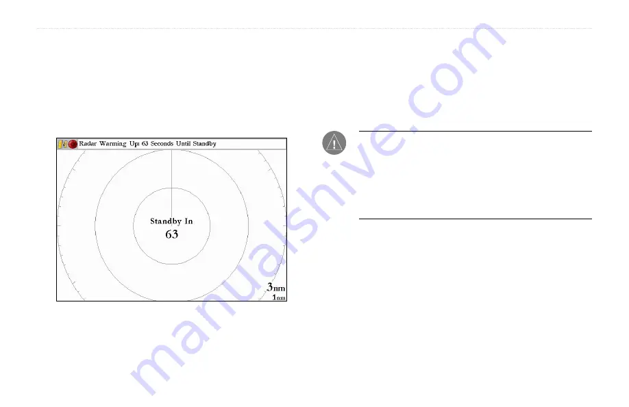
In the Status Bar at the top of the Radar page, the message “Radar 

Warming Up” is displayed with a countdown to Standby Mode. The 

countdown to Standby Mode is also displayed in the middle of the 

radar display. When the countdown reaches zero, the message “Hold 

FCTN to transmit” is displayed.


As a safety feature, the scanner enters Standby Mode after it is 

warmed up. This provides the operator an opportunity to verify 

that the area around the scanner is clear before beginning radar 

transmission. It is important to remember that the microwave energy 

transmitted by the scanner can potentially be dangerous. 

Caution:

 The GMR 20/40 Radar transmits microwave energy that 

has the potential to be harmful to humans and animals. Before 

beginning radar transmission, verify that the area around the 

scanner is clear. The GMR 20/40 transmits a beam approximately 

12° above and below a line extending horizontally from the center 

of the scanner. Avoid looking directly at the scanner as the eyes 

are the most susceptible part of the body.

When the area surrounding the scanner is clear, press and hold the 

FCTN

 key. The message “Do you want to begin radar transmission?” 

is displayed. Select 

Yes

, then press the 

ENTER

 key. Before 

transmission begins, the message “Spinning Up” is displayed while 

the radar antenna reaches nominal rotation speed. When the message 

disappears, the radar begins painting an image. 

 GMR 20/40 O

PERATION

 >

T

HE

 R

ADAR

 P

AGE

Summary of Contents for GMR 20

Page 1: ...GMR 20 40 Marine Radar Owner s Manual...

Page 2: ...to print one copy of this manual or of any revision hereto provided that such electronic or printed copy of this manual must contain the complete text of this copyright notice and provided further tha...

Page 3: ...information such as speci cations and license requirements You can also nd warranty and FCC information in the Appendix Index Use the Index as a key word search to help you nd information more quickly...

Page 4: ...6 Sea Clutter 6 Rain Clutter 7 FTC Fast Time Constant 7 Zoom 8 Target Expansion 8 Trails 9 Guard Zone 9 VRM EBL 10 MARPA 11 MARPA Setup 12 Hide Show Navigation Features 13 Additional Adjustment Menu...

Page 5: ...uld detect the GMR 20 40 as a new network connection Note A software update may be needed for the GMR 20 40 to function properly If the message Incompatible Software Version is displayed when the char...

Page 6: ...ngerous Caution The GMR 20 40 Radar transmits microwave energy that has the potential to be harmful to humans and animals Before beginning radar transmission verify that the area around the scanner is...

Page 7: ...p user con gurable Digital Navigation Data down the right side a Heading Line and Range Rings Soft Key options that allow the user to quickly access functions and change settings may be displayed alon...

Page 8: ...marks at thirty degree increments These tick marks can aid in quickly determining the azimuth to a target The lower scale represents the distance between the Range Rings Heading Line The Heading Line...

Page 9: ...e Radar Adjustment Menu is a numbered list of options that allow direct access to the settings and features most commonly used on the Radar Page There are several adjustment options available Gain Sea...

Page 10: ...Gain Selecting Gain displays the Gain Adjustment Slider When Auto is selected the Scanner Gain is automatically adjusted to provide optimal performance To change the Gain setting 1 Using the ARROW KEY...

Page 11: ...caused by rain at close ranges Selecting Rain Clutter displays the Rain Clutter Adjustment Slider To change the Rain Clutter setting 1 Using the ARROW KEYPAD move the slider to the desired setting 2 P...

Page 12: ...Using the ARROW KEYPAD highlight the desired setting 2 Press the ENTER key to accept the change The Zoom settings can also be selected using the Soft Key options Target Expansion Target Expansion incr...

Page 13: ...Using the ARROW KEYPAD highlight the desired setting 2 Press the ENTER key to accept the change Trails Off Trails On medium To clear the Trails select Clear Trails on the Adjustment Menu or press the...

Page 14: ...ved allowing measurement from one target to another Two V E tools can be activated at the same time The VRM EBL Menu has two areas VRM EBL 1 and VRM EBL 2 Each area has two settings a setting to Show...

Page 15: ...t of Approach and Time to Closest Point of Approach for each target is displayed in the MARPA list Note The MARPA function requires the use of a heading sensor The heading sensor must output the NMEA...

Page 16: ...Target Tracking Target To display the MARPA List Using the ARROW KEYPAD highlight MARPA List and press the ENTER key MARPA List MARPA Setup The MARPA Setup Menu contains settings for Vector Length Tar...

Page 17: ...a an alarm is sounded The Safe Zone can be set to a distance between 01 and 2 nautical miles Time To Safe Zone sounds an alarm if MARPA determines that a target will intersect the Own Vessel Safe Zone...

Page 18: ...settings for Orientation Cross talk Rejection Front of Boat Offset Timed Transmit Timed Transmit XMIT Time and Timed Transmit STBY Time To change a Setup eld option 1 Using the ARROW KEYPAD highlight...

Page 19: ...anchor When Timed Transmit is On the radar refers to the settings in Timed Transmit XMIT Time and Timed Transmit STBY Time If Off is selected the Timed Transmit XMIT Time and Timed Transmit STBY Time...

Page 20: ...culates the bearing relative to own vessel heading Absolute calculates the bearing referring to North Navigation Features there are three selectable Navigation Features Waypoints Bearing Line and Cour...

Page 21: ...s enabled Selecting Begin Transmitting removes the scanner from Standby Mode and after Spinning Up the scanner begins transmitting To select Enter Standby or Begin Transmitting Using the ARROW KEYPAD...

Page 22: ...r Options available on the Map page These options do affect operation of the radar and the Radar page To display the Radar Options 1 Press the ADJ key 2 Using the ARROW KEYPAD highlight Radar Options...

Page 23: ...ermany G Sweden G Greece G United Kingdom I Hungary Cyprus G Ireland Malta Italy G Iceland G Latvia I Norway I Lithuania G Switzerland I I Requires an individual license for operation G can be operate...

Page 24: ...up to 95 at 35 C Beamwidth Horizontal beamwidth of 3 6 nominal Vertical beamwidth of 25 nominal Range GMR 20 24 nm GMR 40 36 nm Wind Velocity Wind speed up to 100 Kts Antenna RPMs 24 rpm Range Ring A...

Page 25: ...tee that interference will not occur in a particular installation If this equipment does cause harmful interference to radio or television reception which can be determined by turning the equipment of...

Page 26: ...ee not to export or re export the Software to any country in violation of the export control laws of the United States of America LIMITED WARRANTY This Garmin product is warranted to be free from defe...

Page 27: ...for warranty repairs Products sold through online auctions are not eligible for rebates or other special offers from Garmin Online auction con rmations are not accepted for warranty veri cation To ob...

Page 28: ...THIS PRODUCT IS INTENDED TO BE USED ONLYAS A NAVIGATIONALAID AND MUST NOT BE USED FOR ANY PURPOSE REQUIRING PRECISE MEASUREMENT OF DIRECTION DISTANCE LOCATION OR TOPOGRAPHY WARNING This product its p...

Page 29: ...mited Warranty 22 M Manually Adjust the Scanner 17 Map Cursor 13 Map Cursor On Off 14 Map Page Radar Overlay 17 MARPA 5 11 MARPA function 11 MARPA List 12 MARPA Setup 12 MARPA Setup Menu 12 MARPA Tab...

Page 30: ...20 40 Owner s Manual INDEX V Variable Range Marker 10 Vector Length 13 Velocity Reference 13 VRM EBL 5 10 W Warming Up 2 Warning and Cautions 24 WARRANTY 22 Waypoints 16 Z Zoom 5 8 Zoom level 8 Zoom S...

Page 31: ......

Page 32: ...armin com Copyright 2005 Garmin Ltd or its subsidiaries Garmin International Inc 1200 East 151st Street Olathe Kansas 66062 U S A Garmin Europe Ltd Unit 5 The Quadrangle Abbey Park Industrial Estate R...

Reviews: