Garmin GMA 340, Maintenance Manual
The Garmin GMA 340 is an advanced aviation audio panel designed with the utmost precision to enhance pilot communication within the cockpit. To ensure a seamless experience, a comprehensive Pilot's Manual is included, available for free download from our website, providing all the necessary instructions and guidance for optimal usage.
Share
Download


Reviews:
No comments
Related manuals for GMA 340

EWA 500.P
Brand: Igloo Pages: 48

EVO
Brand: IFD-NET Pages: 36

100L
Brand: Bartscher Pages: 19

DORICA 400 TBS-PF
Brand: KBS Pages: 61

ST3400H HeliTAWS
Brand: Sandel Pages: 71
ESAGONALE BT
Brand: VALERA Pages: 2
PMA8000G
Brand: PS Engineering Pages: 20

ClearNav
Brand: Nielsen-Kellerman Pages: 86
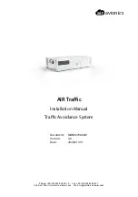
ATD-11
Brand: air avionics Pages: 60
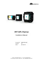
AIR Traffic
Brand: air avionics Pages: 116


