190-01115-01
G3X/G3X Touch Installation Manual - GAP 26 Installation
Rev. AC
Page 5-3
impacted). If the static port is located under the wing, it is recommended that the port be moved to
an alternate location as part of the GAP 26 installation. If port relocation is required, obtain
guidance from the aircraft designer regarding acceptable alternate static port locations.
•
Route all GAP 26 power and ground wires away from any audio wires.
•
To avoid magnetic interference, do not use the airframe to ground the GAP 26 or any other high-
current device. See
for further magnetometer installation considerations.
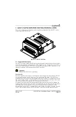
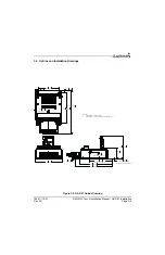
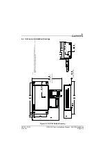
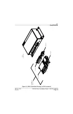
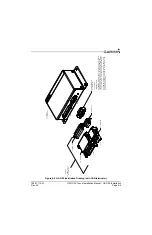
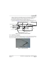
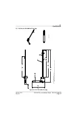
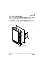
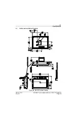
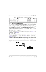
Figure 5-2 GAP 26, Mounting Location Guidance
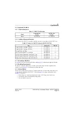
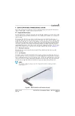
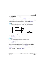
5.5.2 Heater Wiring Configuration
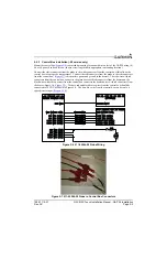
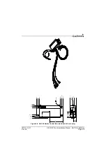
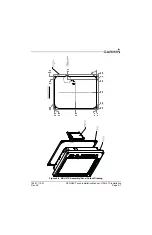
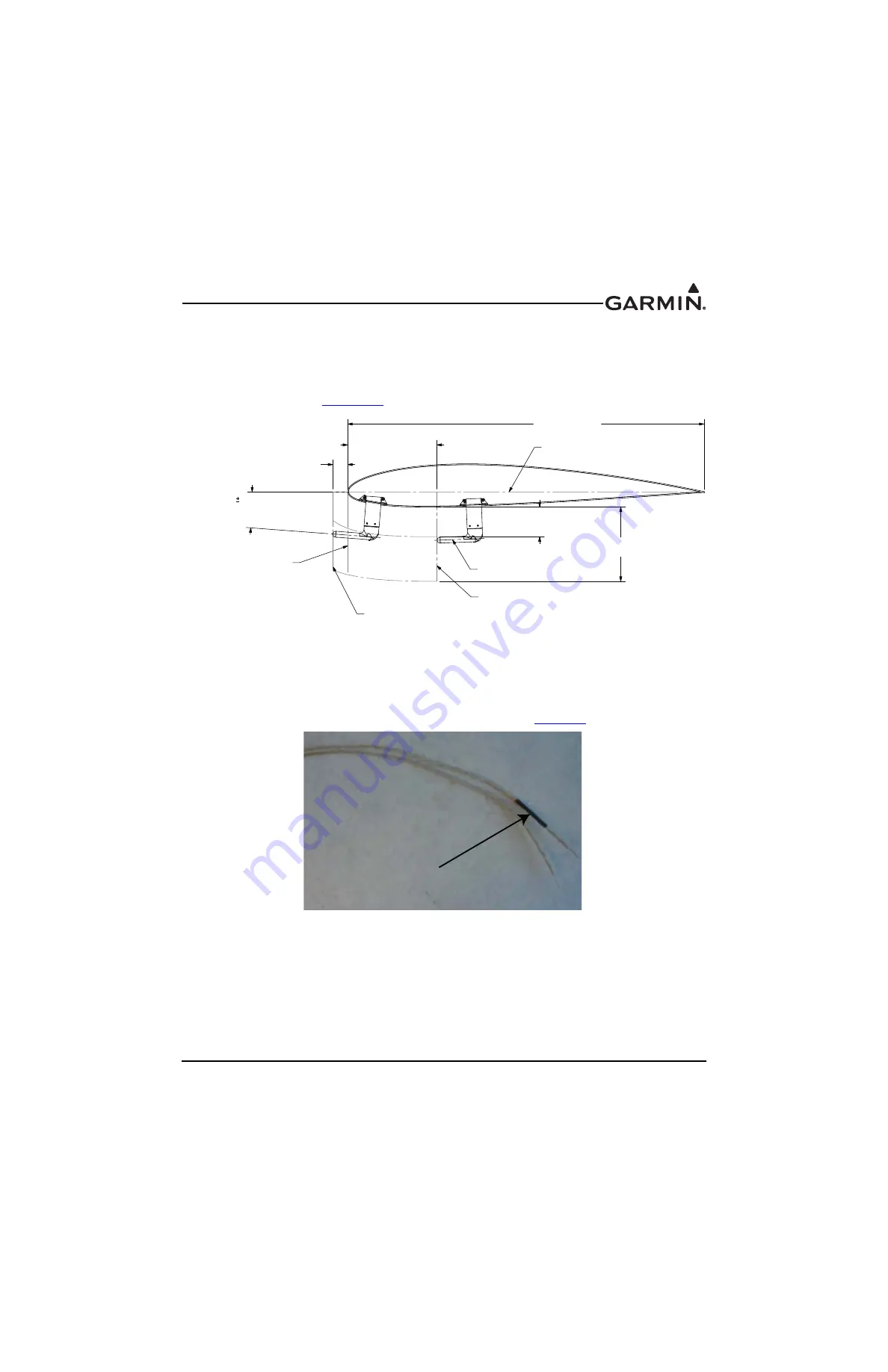
The GAP 26 uses two internal heaters that may be powered by 14 or 28 volt systems. Each of the heaters
has two wires, one of these two wires is “banded” (Figure 5-3) to help identify individual heaters. These
heaters can be connected to a power source as shown in Figure 5-4 and
.
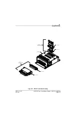
Figure 5-3 GAP 26 Banded Wire
2" MAX ALLOWABLE TIP LOCATION
AHEAD OF WING LEADING EDGE
CHORD LENGTH
25%
OF CHORD LENGTH
4" MIN CENTERLINE
DISTANCE
10" MAX CENTERLINE
DISTANCE
5° MAX
ANGLE BETWEEN CHORD
LINE AND PROBE CENTERLINE
CHORD LINE
WING LEADING EDGE
GARMIN RECOMMENDED
FARTHEST AFT PROBE TIP LOCATION
PROBE CENTERLINE
GARMIN RECOMMENDED
FARTHEST FORWARD PROBE TIP LOCATION
“Banded” Wire