background image

Power-Pole Advanced Boat Control

When the chartplotter is connected to a compatible Garmin trolling motor and a compatible Power-Pole anchor 
system, you can enable advanced boat control functions that use both the Power-Pole anchors and the trolling 
motor.
NOTE: You must enable Anchor Lock on the trolling motor before you can enable advanced boat control.
From the Power-Pole overlay, select 

 to enable these advanced boat control functions.

NOTE: The first time you enable advanced boat control, you must perform a one-time process to set the max 
depth and drag sensitivity. These settings can be adjusted later from the menu on the Power-Pole overlay.
Smart Anchor Selection: The system determines when to use the Anchor Lock function on the trolling motor or 

the Power-Pole anchor system.

Drag Detection: If the Power-Pole shallow water anchors fail to hold the vessel's position, the anchors are 

stowed automatically, the trolling motor attempts to return the vessel to the original position, and it redeploys 
the anchors.

Anchor Jog: When using the trolling motor to move to a different anchor location, the system automatically 

stows the anchors if necessary until the jog procedure is complete. The system then determines whether to 
redeploy the anchors or use the trolling motor Anchor Lock function depending on the depth.

Trolling Motor Direction Control: When the Power-Pole anchors are deployed, you can rotate the angle of the 

trolling motor as needed. This is helpful when you are using LiveScope on the trolling motor and you want to 
view a different angle while anchored.

Auto-Stow: The system automatically stows Power-Pole anchors when you stow the trolling motor.

NOTE: If you want to continue using the Power-Pole anchors when stowing the trolling motor, you must 
disable advanced boat control from the Power-Pole overlay.

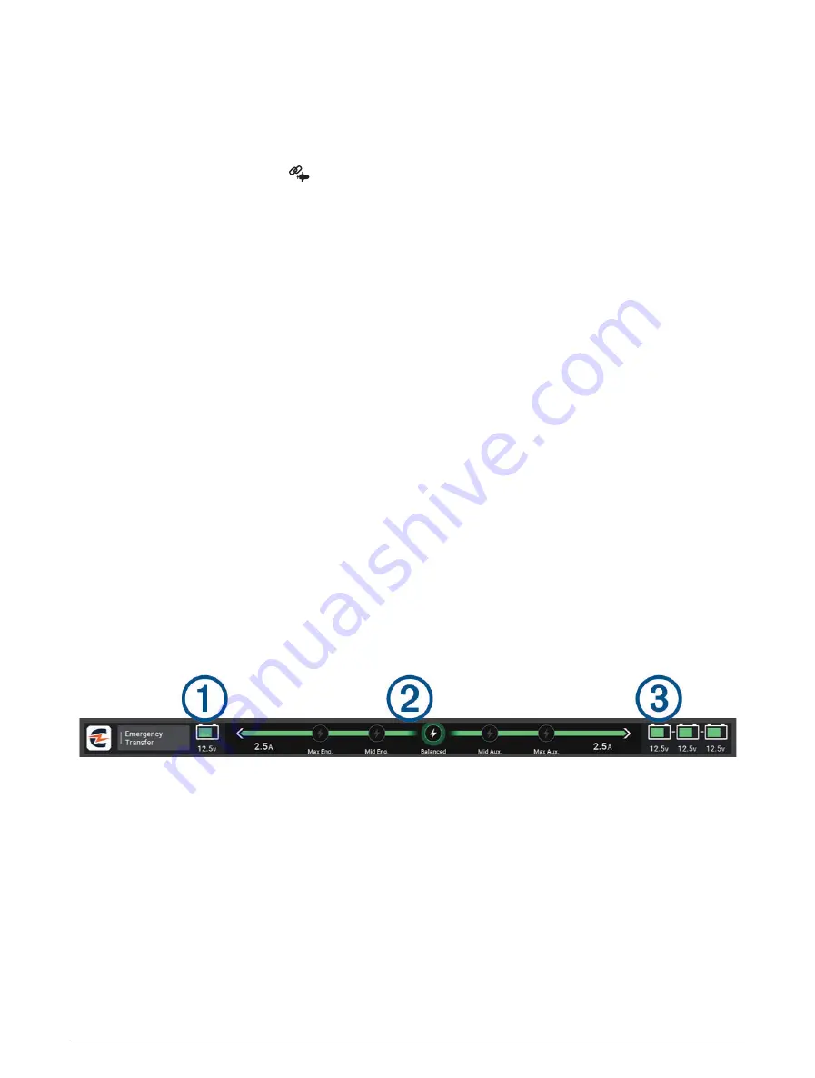
CHARGE Overlay

Before you can add the CHARGE overlay, you must install a CHARGE power management system on your 
vessel and connect it to a C-Monster control system. Both of these systems are Power-Pole products and 
not produced by Garmin. After installing this hardware, you must configure the CHARGE power management 
system and the C-Monster control system so the chartplotter can access and control the charge functions. See 
the owner's manual provided with your CHARGE power management system for more information.
After installing and configuring the CHARGE power management system, you can enable the CHARGE overlay to 
control the system using the chartplotter (

Enabling the Power-Pole Anchor or CHARGE

 Overlay, page 109

).

The layout of the overlay varies based on the size of the chartplotter model. Smaller models may show less text, 
but the functions are the same.

Controlling Third-Party Equipment Installed on Your Boat

111

Summary of Contents for ECHOMAP ULTRA 2

Page 1: ...ECHOMAP ULTRA2 Owner sManual...

Page 2: ...Ltd or its subsidiaries registered in the USA and other countries ECHOMAP Garmin ClearV Garmin Connect Garmin Express Garmin LakeV Garmin Quickdraw Garmin Navionics Vision Panoptix and OneChart are tr...

Page 3: ...ware with the ActiveCaptain App 11 Updating Charts with ActiveCaptain 11 Chart Subscriptions 11 Wireless Sharing 12 Setting Up the Wi Fi Network 12 Connecting Two Compatible ECHOMAP Devices to Share U...

Page 4: ...apping a Body of Water Using the Garmin Quickdraw Contours Feature 32 Adding a Label to a Garmin Quickdraw Contours Map 32 Garmin Quickdraw Community 33 Connecting to the Garmin Quickdraw Community wi...

Page 5: ...48 Clearing the Active Track 48 Managing the Track Log Memory During Recording 48 Configuring the Recording Interval of the Track Log 48 Boundaries 48 Creating a Boundary 49 Converting a Route to a Bo...

Page 6: ...cer Installation Settings 74 Sonar Frequencies 75 Selecting the Transducer Frequency 75 Creating a Frequency Preset 75 Turning On the A Scope 76 Panoptix Sonar Setup 76 Adjusting the RealV Viewing Ang...

Page 7: ...ss 93 Setting the Bow Offset 94 Digital Selective Calling 94 Networked Chartplotter and VHF Radio Functionality 94 Turning On DSC 94 DSC List 94 Viewing the DSC List 94 Adding a DSC Contact 95 Incomin...

Page 8: ...ting Up the Power Pole Anchor 110 Power Pole Overlay 110 Power Pole Advanced Boat Control 111 CHARGE Overlay 111 Mercury Troll Control Features 112 Adding the Mercury Troll Control Overlay 112 Mercury...

Page 9: ...from a Category 127 DAB Presets 127 Saving a DAB Station as a Preset 127 Selecting a DAB Preset from a List 127 Removing DAB Presets 127 SiriusXM Satellite Radio 127 Locating a SiriusXM Radio ID 128 A...

Page 10: ...42 Restoring Backup Data to a Chartplotter 142 Saving System Information to a Memory Card 142 Appendix 143 ActiveCaptain and Garmin Express 143 Garmin Express App 143 Installing the Garmin Express App...

Page 11: ...all models The Garmin website at support garmin com presents up to date information about your product The support pages will provide answers to frequently asked support questions and you can download...

Page 12: ...Garmin Marine Network cable port for connection to compatible Panoptix GCV and ECHOMAP devices NOTE This device is not compatible with some Garmin Marine Network devices such as GPSMAP GSD and radar d...

Page 13: ...your chartplotter not all feature buttons are visible are on the home screen Swipe right or left to view the additional feature buttons On some menu buttons select the button to enable the option A gr...

Page 14: ...signals The time and date are set automatically based on the GPS position 1 Turn on the device 2 Wait while the device locates satellites It may take 30 to 60 seconds to acquire satellite signals To v...

Page 15: ...on Home Opens the home screen TIP Touch and drag to scroll through the home screen items Info Opens the Information menu Appears when there are warnings to review in the Warning Manager Opens the opti...

Page 16: ...f your chartplotter For example the Sonar tab displays the views and screens related to the sonar feature TIP To view the available categories tabs you may need to click and drag a tab to scroll left...

Page 17: ...ect an option Adjusting the Backlight 1 Select Settings System Sounds and Display Backlight 2 Adjust the backlight TIP From any screen press repeatedly to scroll through the brightness levels This can...

Page 18: ...turning on the chartplotter Recommended Startup Image Dimensions For the best fit for the startup images use an image that has the following dimensions in pixels Display resolution Image width Image...

Page 19: ...o Yes Customizing the Data Overlays You can customize the data in the data overlays shown on a screen 1 Select an option based on the type of screen you are viewing From a full screen view select Edit...

Page 20: ...ctiveCaptain App You can connect a mobile device to the ECHOMAP Ultra 2 device using the ActiveCaptain app The app provides a quick and easy way for you to interact with your ECHOMAP Ultra 2 device an...

Page 21: ...ou can use the ActiveCaptain app to download and transfer the latest chart updates for your device To shorten download time and conserve storage space you can download only the areas of the chart you...

Page 22: ...e other device as the client You can only connect two compatible ECHOMAP devices at a time The host device can be connected to other wireless devices like your phone or tablet while it is connected wi...

Page 23: ...Enter the chartplotter password Managing the Wi Fi Network Changing the Wi Fi Host If there are multiple chartplotters with Wi Fi technology on the Garmin marine network you can change which chartplo...

Page 24: ...sories used NOTE 3D chart views are available with premium charts in some areas You can access the charts and 3D chart views by selecting Charts Nav Chart Shows navigation data available on your pre l...

Page 25: ...iveCaptain App page 10 3 After the ActiveCaptain app connects to the chartplotter make sure your mobile device is connected to the internet 4 In the ActiveCaptain app select Chart My Charts and verify...

Page 26: ...art Chart Symbols This table contains some of the common symbols you might see on the detailed charts Icon Description Buoy Information Marine services Tide station Current station Overhead photo avai...

Page 27: ...bject on the Navigation chart or the Fishing chart 1 From the Navigation chart or Fishing chart select a location or object A list of options appears The options that appear vary based on the location...

Page 28: ...se visual sightings and steer to avoid land shallow water and other dangerous objects NOTE The Fishing chart is available with premium charts in some areas NOTE Auto Guidance is available with premium...

Page 29: ...tures using the ActiveCaptain app Activating a Marine Chart Subscription page 15 Mariner s Eye 3D Provides a view from above and behind the boat for a three dimensional navigation aid Fish Eye 3D Prov...

Page 30: ...onsibility to heed all posted water related guidance to remain aware of your surroundings and to use safe judgment in on and around the water at all times Failure to heed this warning could result in...

Page 31: ...peed Range Yellow 0 to 1 knot Orange 1 to 2 knots Red 2 or more knots Showing Tides and Current Indicators NOTE This feature is available with premium charts in some areas You can show static or anima...

Page 32: ...ection in which the triangle is pointing indicates the direction in which the AIS vessel is moving Target is selected Target is activated The target appears larger on the chart A green line attached t...

Page 33: ...ed AIS target the projected course of the target is calculated based on the course over ground and the rate of turn information The direction in which the target is turning which is also based on the...

Page 34: ...0 Failure to set audible alarms could lead to injury or property damage Before you can set a collision alarm you must connect an AIS device to the same network as a compatible chartplotter The safe zo...

Page 35: ...location You can view AIS ATONs on the chart when the chartplotter is connected to a compatible AIS radio To show AIS ATONs from a chart select Layers Chart Navaid ATONs You can view more information...

Page 36: ...Transmission lost Transmission test Appears when a vessel initiates a test of their distress signal device and does not represent a true emergency Transmission test lost Enabling AIS Transmission Test...

Page 37: ...ing to the boat My Vessel Layer Settings page 28 Manage User Data Shows and hides user data such as waypoints boundaries and tracks and opens user data lists User Data Layer Settings page 29 Other Ves...

Page 38: ...option Vessel Icon Sets the icon that represents your present location on the chart Laylines Settings To use the laylines features you must connect a wind sensor to the chartplotter When in sailing m...

Page 39: ...that are not supported by your installed charts or your present location If you make changes to those settings the changes will not impact the chart view NOTE Not all settings apply to all charts view...

Page 40: ...d fishing a maximum of five depth ranges can help reduce map clutter The depth ranges apply to all charts and all bodies of water Some Garmin LakeV and premium supplemental charts have multiple depth...

Page 41: ...TE You can set the Map Orientation and Vessel Orientation settings separately for two navigation charts used in a combination page Detail Adjusts the amount of detail shown on the map at different zoo...

Page 42: ...amount of saved data depends on the size of your memory card your sonar source and the speed of your boat as you record data You can record longer when you use a single beam sonar It is estimated that...

Page 43: ...tours 2 Use the map and search features to locate an area to download The red dots represent Garmin Quickdraw Contours maps that have been shared for that area 3 Select Select Download Region 4 Drag t...

Page 44: ...Quickdraw Community If your device does not have Wi Fi technology you can access the Garmin Quickdraw Community using the Garmin Connect website If your device has Wi Fi technology you should access...

Page 45: ...o avoid groundings or hazards that could result in vessel damage personal injury or death The Auto Guidance feature is based on electronic chart information That data does not ensure obstacle and bott...

Page 46: ...to provide general route guidance or to identify proper channels and are not intended to be precisely followed Always defer to the navaids and conditions on the water when navigating to avoid groundi...

Page 47: ...ouch and drag up and down to scroll through the list of nearest destinations Setting and Following a Direct Course Using Go To WARNING When using Go To a direct course and a corrected course may pass...

Page 48: ...ect Use Chart select the location and select Create Waypoint To create the waypoint using a range distance and bearing select Enter Range Bearing and enter the information Marking an MOB Location Sele...

Page 49: ...lect Info Waypoints 2 Select a waypoint 3 Select Review Edit Position 4 Indicate a new location for the waypoint To move the waypoint using coordinates select Enter Coordinates enter the new coordinat...

Page 50: ...Auto Guidance is available with premium charts in some areas Before you can navigate to a waypoint you must create a waypoint 1 Select Info Waypoints 2 Select a waypoint 3 Select Navigate To 4 Select...

Page 51: ...e route The starting point can be your present location or another location 3 Select Add Turn 4 Select the location of the next turn on the chart 5 Select Add Turn 6 If necessary repeat steps 4 and 5...

Page 52: ...st create and save at least one route Creating and Saving a Route page 41 1 Select Info Routes NOTE Auto Guidance is available with premium charts in some areas 2 Select a route 3 Select Navigate To 4...

Page 53: ...other obstacles that may be in your path All route and navigation lines displayed on the chartplotter are only intended to provide general route guidance or to identify proper channels and are not in...

Page 54: ...the navigation chart and select Adjust Path 3 Select a location on the path 4 Drag the point to a new location 5 If necessary select a point and select Remove 6 Select Done Canceling an Auto Guidance...

Page 55: ...path Select Settings Preferences Navigation Auto Guidance Preferred Depth Sets the minimum water depth based on chart depth data that your boat can safely travel over NOTE The minimum water depth for...

Page 56: ...s a wide clearance from obstacles in open water even if you set the Shoreline Distance setting to Near or Nearest As a result the chartplotter may not reposition the Auto Guidance line unless the dest...

Page 57: ...k as a Route 1 Select Info Tracks Saved Tracks 2 Select a track 3 Select Review Edit Track Save as Route Browsing for and Navigating a Recorded Track Before you can browse a list of tracks and navigat...

Page 58: ...ck based on a distance between points select Distance Change and enter the distance To record the track based on a time interval select Time Change and enter the time interval To record the track plot...

Page 59: ...larms alert you when you are within a specified distance of a set boundary This can be helpful when attempting to avoid certain areas or when you should be very alert in certain areas 1 Select Info Bo...

Page 60: ...ine is white This indicates the boat must increase speed to reach the start line on time When the end point is past the start line the line is red This indicates the boat must reduce speed to avoid a...

Page 61: ...ines on the navigation chart Laylines can be very helpful when racing From the Navigation chart select Layers My Vessel Laylines Setup Sailing Ang Allows you to select how the device calculates laylin...

Page 62: ...one set of data at a time Showing Polar Data in Data Fields Before you can view polar data you must import a polar table from a memory card Importing a Polar Table Manually page 52 1 Open the screen t...

Page 63: ...1 Measure the distance If the transducer is installed at the water line or anywhere above the end of the keel measure the distance from the transducer location to the keel of the boat Enter this valu...

Page 64: ...udder while tacking and gybing Wind Hold You can set the autopilot to maintain a specific bearing relative to the apparent or true wind angle You must connect a compatible wind sensor the same NMEA 20...

Page 65: ...lly transitions the autopilot from Wind Hold to Heading Hold and initiates rudder steering To adjust the wind hold angle in increments of 10 select 10 or 10 NOTE You can adjust the settings so that th...

Page 66: ...a heading sensor is connected 1 From a chart select Layers My Vessel Heading Line Angle Markers 2 If necessary select Source and select an option To automatically use the available source select Auto...

Page 67: ...nar views to suit your needs you can create a custom combination screen Creating a New Combination Page page 9 Stopping the Transmission of Sonar Signals To disable the active sonar from the sonar scr...

Page 68: ...quency sonar provides a detailed picture of the fishing environment around the boat in a detailed representation of structures the boat is passing over Traditional transducers emit a conical beam The...

Page 69: ...del does provide built in SideV sonar you need a compatible SideV transducer SideV scanning sonar technology shows you a picture of what lies to the sides of the boat You can use this as a search tool...

Page 70: ...optix Sonar Views To receive Panoptix sonar you need a compatible transducer The Panoptix sonar views allow you to see all around the boat in real time You can also watch your bait underwater and bait...

Page 71: ...is sonar view shows a two dimensional view of what is below the boat and can be used to see a bait ball and fish Panoptix down view history in a scrolling sonar view Boat Range Trails Drop shot rig Bo...

Page 72: ...LiveV Forward Sonar View This sonar view shows a two dimensional view of what is in front of the boat and can be used to see a bait ball and fish Boat Range Fish Trails Bottom 62 Sonar Fishfinder...

Page 73: ...ws a three dimensional view of what is in front of the transducer This view can be used when you are stationary and you need to see the bottom and the fish approaching the boat Color legend Boat Ping...

Page 74: ...his sonar view shows a three dimensional view of what is below the transducer and can be used when you are stationary and want to see what is around your boat Color legend Boat Sonar beam Range Fish B...

Page 75: ...s a three dimensional view of what is behind your boat as you are moving and shows the entire water column in 3D from the bottom to the top of the water This view is used for finding fish Color legend...

Page 76: ...sonar decreases as your speed rises above 8 knots To see the FrontV sonar view you must install and connect a compatible transducer such as a PS21 transducer You may need to update the transducer soft...

Page 77: ...ircular depth scale indicating what is beneath your boat It is organized as a ring that starts at the top and progresses clockwise Depth is indicated by the scale inside the ring Sonar information fla...

Page 78: ...ct To select the transducer manually learn the range for the installed transducer select the transducer to change select the option that matches the installed transducer such as Dual Beam 200 77 kHz o...

Page 79: ...iew 1 From the sonar view select Sonar Setup Source Rename Sources 2 Enter the name Creating a Waypoint on the Sonar Screen 1 From a sonar view drag the screen or select 2 Select a location 3 Select 4...

Page 80: ...zoom out until the screen returns to a full screen view Adjusting the Level of Detail You can control the level of detail and noise shown on the sonar screen either by adjusting the gain for tradition...

Page 81: ...lect Default Sonar Setup NOTE Not all options and settings apply to all models and transducers These settings apply to the following types of transducers Traditional Garmin ClearV SideV These settings...

Page 82: ...information on the screen longer For most situations the Default setting provides a good balance between a quickly scrolling image and less distorted targets 1 From a sonar view select Sonar Setup Scr...

Page 83: ...s clutter or noise near the water surface It also allows for the display of targets near the surface that are otherwise hidden or masked by surface noise Sonar Appearance Settings From a sonar view se...

Page 84: ...t sets the alarm to sound when fish of all sizes are detected sets the alarm to sound only when medium or large fish are detected sets the alarm to sound only when large fish are detected Advanced Son...

Page 85: ...ansducer element which enables you to change the frequency quickly using the presets as the water and your goals change Viewing two frequencies concurrently using the split frequency view allows you t...

Page 86: ...Adjusting the RealV Viewing Angle and Zoom Level You can change the viewing angle of the RealV sonar views You can also zoom in and out of the view From a RealV sonar view select an option To adjust...

Page 87: ...pth Manually adjusting the range enables you to view a specified range The bottom can appear on the screen as long as it appears within the range you have set Manually reducing this option can reduce...

Page 88: ...t 10 seconds It turns red and sounds an alarm when the system detects an obstruction or the depth is less than the entered value LiveV and FrontV Appearance Settings From a LiveV or FrontV Panoptix so...

Page 89: ...am Narrow beam widths allow you to see deeper and farther Wider beam widths allow you to see more coverage area This applies to Panoptix transducers in the FrontV LiveV Down and LiveV Forward sonar vi...

Page 90: ...the compass the transducer must be installed far enough away from the trolling motor to avoid magnetic interference and deployed in the water Calibration must be of sufficient quality to enable the i...

Page 91: ...view a specified range which can be useful for tracking a bottom that has large terrain changes such as a drop offs or cliffs The bottom can appear on the screen as long as it appears within the rang...

Page 92: ...rward views compresses the forward range farther away from the boat and expands the range closer to the boat This allows you to see closer objects more clearly while keeping farther objects on the scr...

Page 93: ...lot Configuration NOTICE To avoid damage to your boat the autopilot system should be installed and configured by a qualified marine installer Specific knowledge of marine steering and electrical syste...

Page 94: ...ng the Step Steering Increment 1 From the autopilot screen select Autopilot Setup Step Turn Size 2 Select an increment Setting the Power Saver You can adjust the level of rudder activity 1 From the au...

Page 95: ...enabled You can repeat these steps to disable the feature again Autopilot Overlay Bar NOTE Not all options are available on all autopilot models Autopilot status Engages and disengages heading hold S...

Page 96: ...re certain the water is clear of obstacles The autopilot can steer the boat in preset patterns for fishing and it can perform other specialty maneuvers such as U turns and Williamson turns Following t...

Page 97: ...Steering Cloverleaf 2 If necessary select Length and select a distance 3 Select Engage Port or Engage Starboard Setting Up and Following a Search Pattern You can use the search pattern to steer the bo...

Page 98: ...s a tool that enhances your capability to operate your boat It does not relieve you of the responsibility of safely operating your boat Avoid navigational hazards and never leave the helm unattended Y...

Page 99: ...o a helm throttle and helm control device You are responsible for the safe and prudent operation of your vessel The autopilot is a tool that enhances your capability to operate your boat It does not r...

Page 100: ...e autopilot when it reaches the end of a route The FishPoint option maintains the position but does not maintain the heading The DriftPoint option allows the boat to drift with the wind or current whi...

Page 101: ...stops acceleration and turns When stowing or deploying the motor be aware of slick surfaces around the motor Slipping when stowing or deploying the motor may result in injury You can connect the Forc...

Page 102: ...ol bar allows you to control a Force trolling motor and see the status of the motor Select an item to engage it The button illuminates when selected Select the item again to disengage it Trolling moto...

Page 103: ...safe operation of your boat When using the Manual setting for the Arrival Mode option you must be ready to take control of the boat Auto Power On Turns on the trolling motor when you apply power to t...

Page 104: ...ition reports If you have a Garmin NMEA 2000 VHF radio connected to your chartplotter these features are also enabled The chartplotter allows you to quickly set up and send individual routine call det...

Page 105: ...ed to a compatible VHF radio with NMEA 2000 and you initiate a man overboard DSC distress call from the radio the chartplotter shows the man overboard screen and prompts you to navigate to the man ove...

Page 106: ...ked vessel and a blue flag indicates the last reported position of the vessel 1 From a chart or 3D chart view select Layers Other Vessels DSC DSC Trails 2 Select the number of hours to show tracked ve...

Page 107: ...call Making an Individual Routine Call to an AIS Target 1 From a chart or 3D chart view select an AIS target 2 Select AIS Vessel Call with Radio 3 If necessary select Channel and select a new channel...

Page 108: ...Layout To add a page to this set of gauge pages select Add Page To remove a page from this set of gauge pages select Remove Page To change the order of this page in the set of gauge pages select Move...

Page 109: ...ge 99 1 From the engine gauges screen select Installation Engine Selection Num Engines 2 Select First Engine 3 Select the engine to display in the first gauge 4 Repeat for the remaining engine bars En...

Page 110: ...t functions Helm Master Tank level information Hold a tank to view detailed tank level sensor information Status icons GPS signal strength Helm Master Select to set the Fish Point settings Helm Master...

Page 111: ...tor is on Serious engine damage will occur Low battery voltage Check the battery and battery connections and tighten all loose battery connections Return to port soon if tightening the battery connect...

Page 112: ...er system equipped with a digital engine control DEC system Steer Friction Sets the friction on the steering wheel The friction adjusts automatically according to the engine speed Available on the Hel...

Page 113: ...olant pressure oil pressure and other data Select Vessel Mercury to view the Mercury engine gauges Engine voltage or Mercury Steering Angle2 Boat status Boat speed Fuel Transmission gear Engine speed...

Page 114: ...Tanks The fuel level is set to maximum capacity If you have added less than a full tank of fuel select Add Fuel to Boat and enter the amount added To specify the total fuel in the vessel tanks select...

Page 115: ...is replaced by the Close Hauled Gauge 4 Select an option To set the maximum and minimum values that appear when the upwind close hauled wind gauge appears select Change Upwind Scale and set the angles...

Page 116: ...tter and receiving satellite signals to send and receive messages using the chartplotter Messages received and sent by the inReach device are grouped as conversations that are identified using the nam...

Page 117: ...ations Send Preset Message 2 Select a preset or check in message 3 Select Send Starting a New Conversation 1 From the InReach page select Conversations Start Conversation 2 Add recipients To include a...

Page 118: ...ach SOS Call You must pair a compatible inReach device with your chartplotter before you can send an inReach SOS call using the chartplotter 1 From any screen select SOS 2 Select Activate inReach SOS...

Page 119: ...ld save the custom image to the Garmin folder on the memory card You can also adjust the view and placement of the image Controlling Third Party Equipment Installed on Your Boat Power Pole Anchor Syst...

Page 120: ...trol the Power Pole anchor with the chartplotter you must enable the overlay Enabling the Power Pole Anchor or CHARGE Overlay page 109 and set the Power Pole installation mode Setting Up the Power Pol...

Page 121: ...Anchor Lock function depending on the depth Trolling Motor Direction Control When the Power Pole anchors are deployed you can rotate the angle of the trolling motor as needed This is helpful when you...

Page 122: ...ury Troll Control Features WARNING You are responsible for the safe and prudent operation of your vessel The Mercury troll control features do not steer the boat for you and do not avoid navigational...

Page 123: ...ercury Cruise Control does not steer the boat for you and does not avoid navigational hazards Failure to safely operate your boat could result in an accident causing property damage serious personal i...

Page 124: ...the engines could result in an accident causing property damage serious personal injury or death When your chartplotter is connected to a compatible Mercury engine you can view engine data using the M...

Page 125: ...overlay select Sport Exhaust On TIP You can select from the menu bar to quickly open the overlay TIP You can also enable the Sport Exhaust setting from the Mercury gauges page menu Mercury Active Trim...

Page 126: ...enable the Optimus overlay to control the Optimus system Activating the Optimus Overlay Bar page 116 When necessary the Optimus system provides messages with information instructions and alerts about...

Page 127: ...Home Mode WARNING In the event of a steering failure Optimus Limp Home mode becomes available Limp Home mode is a system override that may severely limit your boat s control It should only be used in...

Page 128: ...n is always visible Tide and Current Overlays page 119 Current Station Information WARNING Tide and current information is for information purposes only It is your responsibility to heed all posted wa...

Page 129: ...on page Adding Tide and Current Overlays 1 From the page where you want to add the overlay select Edit Overlays TIP You can also select from the menu bar to quickly change the overlays 2 Select Top Ba...

Page 130: ...3 Select Tides Currents or Celestial Warning Manager During an active warning an indicator appears on the menu bar The Warning Manager displays a color coded alarm icon and prioritizes alarm messages...

Page 131: ...automatically detect the stereos If you have a compatible third party stereo connected to the NMEA 2000 network you may be able to control the stereo using the chartplotter NOTE Not all features are...

Page 132: ...g the Home Zone page 123 1 From the media screen select Audio Levels 2 Select or to adjust the audio levels you want to change Muting the Media Volume 1 From the media screen select 2 If necessary sel...

Page 133: ...le stereos connected to the chartplotter or have a stereo or stereos with multiple speaker zones connected to the chartplotter you must designate one speaker zone on one stereo as the home zone The pl...

Page 134: ...physical switch on the ignition wire the red wire all of the synchronized stereos in the group turn off and on together This applies to all of the synchronized stereos in the group whether or not a s...

Page 135: ...ices and sources support the All option for the Repeat control From the media screen select an option Select Repeat All Select Browse Repeat All Setting Songs to Shuffle From the media screen select a...

Page 136: ...eo is connected to the proper DAB equipment and set to the correct tuner region DAB Playback page 126 Saving a Station as a Preset 1 From an applicable media screen tune to the station to save as a pr...

Page 137: ...s 2 Select a station from the list Selecting a DAB Station from a Category 1 From the DAB media screen select Browse Categories 2 Select a category from the list 3 Select a station from the list DAB P...

Page 138: ...l 5 If the service is not activated within the hour go to http care siriusxm com refresh or contact SiriusXM Listener Care by phone at 1 866 635 2349 Customizing the Channel Guide SiriusXM radio chann...

Page 139: ...tal control settings to their default values the passcode value is reset to 0000 1 From the media menu select Installation Factory Defaults 2 Select Yes Changing a Parental Passcode on a SiriusXM Radi...

Page 140: ...s the device to display day or night colors You can select the Auto option to allow the device to set day or night colors automatically based on the time of day Startup Image Sets the image that appea...

Page 141: ...based on the location of this station You can also select to use this display as a stand alone individual display instead of grouping it with other displays to make a station Display Order Sets the or...

Page 142: ...the north reference 000 Magnetic sets the magnetic north as the north reference Position Format Sets the position format in which a given location reading appears Do not change this setting unless yo...

Page 143: ...ance path Select Settings Preferences Navigation Auto Guidance Preferred Depth Sets the minimum water depth based on chart depth data that your boat can safely travel over NOTE The minimum water depth...

Page 144: ...ep 6 review the placement of the Auto Guidance line and determine whether the line safely avoids known obstacles and the turns enable efficient travel Auto Guidance maintains a wide clearance from obs...

Page 145: ...ices and sensors connected to the Garmin Marine Network and the NMEA 2000 network 1 Select Settings Communications 2 Select Marine Network or NMEA 2000 Setup Device List 3 Select a device from the lis...

Page 146: ...unding in all circumstances It is your obligation to ensure safe operation of the vessel CAUTION The Beeper setting must be turned on to make alarms audible Sounds and Display Settings page 130 Failur...

Page 147: ...ance from the bow of the vessel to the bottom of the water These anchor settings are used to calculate the Target Anchor Rode date field Temp Offset Allows you to set an offset value to compensate for...

Page 148: ...Measure the distance If the transducer is installed at the water line or anywhere above the end of the keel measure the distance from the transducer location to the keel of the boat Enter this value...

Page 149: ...o the Fuel Tank option The chartplotter uses information from the tank level sensors so you do not need to do manually enter fuel information after you fill up the tanks Fuel Capacity Allows you to en...

Page 150: ...alues select Reset Station Settings This restores the default configuration settings but does not remove saved user data maps or software updates To clear saved data such as waypoints and routes selec...

Page 151: ...Save All to Card 3 If necessary select the memory card to copy the data to 4 Select an option To create a new file select Add New File and enter a name To add the information to an existing file selec...

Page 152: ...p Data to a Computer 1 Insert a memory card into the card slot 2 Select Info Manage User Data Data Transfer Save to Card 3 Select a file name from the list or select Add New File 4 Select Save to Card...

Page 153: ...pp page 143 You should use the Garmin Express app for faster data transfer of larger downloads and updates and to avoid possible data charges with some mobile devices Function ActiveCaptain mobile app...

Page 154: ...armin folder on the memory card 4 Remove the memory card from your device 5 Open the Garmin Express app on your computer 6 Insert the memory card into your computer 7 If necessary select Get Started 8...

Page 155: ...nutes while the update process completes 16 When prompted leave the memory card in place and restart the chartplotter 17 Remove the memory card NOTE If the memory card is removed before the device res...

Page 156: ...update onto the memory card install the software on the chartplotter Updating the Device Software Using a Memory Card page 146 Updating the Device Software Using a Memory Card To update the software...

Page 157: ...e 4 Hold Home or for at least six seconds Copying Screenshots to a Computer 1 Remove the memory card from the chartplotter and insert it into a card reader that is attached to a computer 2 From Window...

Page 158: ...ld be the map datum and position format of the device may not match the map datum and position format originally used to mark the waypoint Position format is the way in which the GPS receiver s positi...

Page 159: ...Garmin ClearV and Garmin SideV CHIRP 600 W Sonar depth6 701 m 2 300 ft at 77 kHz 100 Series Models Dimensions device only W x H x D 294 x 191 x 80 mm 115 8 x 71 2 x 33 16 in Dimensions in bail mount w...

Page 160: ...PGN Information Transmit and Receive PGN Description 059392 ISO acknowledgment 059904 ISO request 060160 ISO transport protocol data transfer 060416 ISO transport protocol connection management RTS g...

Page 161: ...te and waypoint info Receive PGN Description 065240 ISO commanded address 126983 Alert 126985 Alert text 126987 Alert threshold 126988 Alert value 126992 System time 127237 Heading tack control 127245...

Page 162: ...gation AtoN report 129283 Cross track error 129284 Navigation data 129285 Navigation Route and waypoint information 129794 AIS class A static and voyage related data 129798 AIS SAR aircraft position r...

Page 163: ...PGN Description 130578 Vessel speed components Appendix 153...

Page 164: ...support garmin com GUID 9A17B80C F7A5 4535 8E7D E8F0ECD1DCD4 v1 October 2023...

Reviews: