


echo Installation Instructions
3
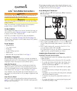
Installing the transducer on a trolling Motor
Notice
Do not cut the transducer cable. Cutting the transducer cable will void your
warranty.
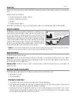
1. Feed the 20 in. (50 cm) cable tie
➊
through the slot on the transducer
mount
➋
, with the ridges of the cable tie facing up, until equal lengths
extend on both sides of the mount.
For use in cold water or in areas with heavy timber or debris, use a metal
4–5 in. worm gear clamp (not included) instead of the cable tie.
➋
➊
➌
➍
➎
2. Position the mount gasket
➌
on the curved top of the transducer mount.
3. Place the transducer mount against the body of the trolling motor with the
front of the transducer pointed away from the propeller.
4. Secure the 20 in. (50 cm) cable tie around the body of the trolling motor,
but do not fully tighten the cable tie.
5. Properly align the gasket between the transducer mount and the body of
the trolling motor, and tighten the cable tie.
If necessary, trim the excess cable tie.
6. Position the transducer so that it will be parallel with the bottom when
in use, tighten the 10-32 locking nut
➍
until it touches the mounting
bracket, and tighten
1
/
4
turn more (do not overtighten).
7. Use the supplied 5
1
/
2
in. (14 cm) cable ties
➎
to secure the transducer
cable to the motor shaft.
If necessary, fill the forward-facing portion (except the cable tie pocket)
of the transducer mount with sealant to avoid accumulation of debris.
8. Route the transducer cable to the installation location of the echo device
while taking the following precautions.
• Avoid routing the cable close to electrical wires or other sources of
electrical interference.
• Make sure that the cable will not become pinched when the trolling
motor is deployed and recovered.
Installing the Swivel Mount
1. Select a mounting location (
).
2. Prepare the swivel-mount base (
3. Fasten the mount with the cables installed in the mount (
without the cables installed in the mount (
Selecting a Swivel-Mount Location
Select a location to install the swivel mount, while considering these
guidelines.
• The location provides a clear view of the screen and access to the keys on
the echo.
• The location is sturdy enough to support the device and the mount.
• You can route the cables either from under the swivel mount, or from
behind the device.
• The location is the appropriate distance from a compass (
Preparing the Swivel-Mount Base Installation
Notice
Use pan-head screws or bolts when securing the swivel-mount base. Screws
or bolts with countersunk heads will damage the base.
1. After you have chosen the location to install the swivel mount (
determine whether you will attach the mount to the surface using screws
or bolts, and choose the appropriate fastening hardware:
• To attach the base with screws, use self-tapping, pan-head wood
screws, either size #8 or a diameter of
5
/
32
in. (4 mm), with an
appropriate drill bit for the pilot hole.
• To attach the base with bolts, use pan-head bolts, either size #8 or a
diameter of
5
/
32
in. (4 mm), with the appropriate washers and nuts. Use
a drill bit of the same diameter as the bolt.
2. Separate the swivel base from the mount.
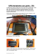
3. If you plan to route the cables from
under the mounting surface, orient the
swivel base so that the pass-through
holes
➊
face the desired direction.
4. Using the swivel base as a template,
mark the pilot hole locations
➋
.
5. If you plan to route the cables from
under the mounting surface, mark the
location in the center
➌
.
6. Using the appropriate drill bit for the
hardware, drill the three pilot holes.
7. If you plan to run the power and transducer cables from under the
mounting surface, use a
5
/
8
in. (16 mm) drill bit to drill a hole through the
mounting surface at the location you marked in step 5.
➊
➌
➋