background image

Garmin G1000 Cockpit Reference Guide for the DA42-L360

190-01062-01  Rev. A 

Appendix

78

Flight

Instruments

EIS

Nav/Com/

XPDR/Audio

AFCS

GPS Nav

Flight

Planning

Pr

ocedur

es

Hazar

d

Avoidance

Additional

Featur

es

Abnormal

Oper

ation

Annun/

Alerts

Appendix

Index

BRG2

Cycles the Bearing 2 Information 
Window through NAV2 or GPS/waypoint 
identifier and GPS-derived distance 
information

, and ADF/frequency.

ALT UNIT

Displays softkeys for setting the altimeter 
and BARO settings to metric units

METERS

When enabled, displays altimeter in 
meters

IN

Press to display the BARO setting as 
inches of mercury

HPA

Press to display the BARO setting as 
hectopacals

STD BARO

Sets barometric pressure to 29.92 in Hg 
(1013 hPa)

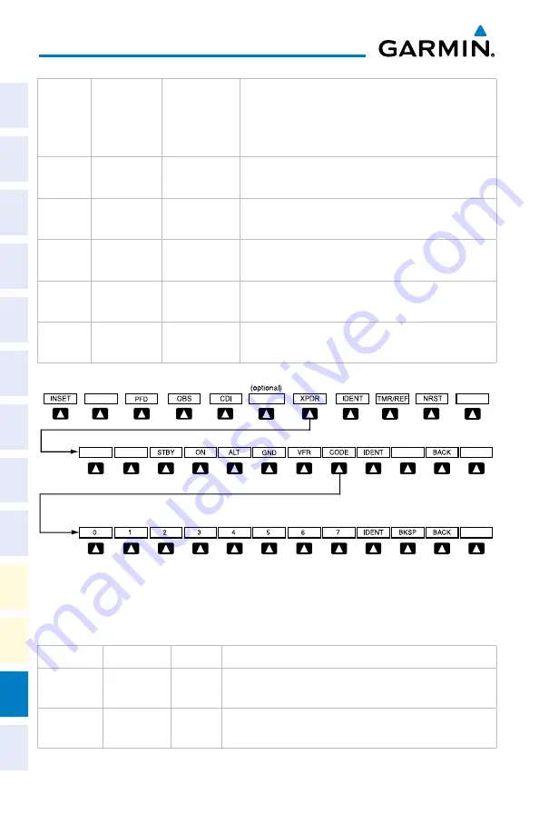
Transponder Softkeys

Press the 

BACK

 Softkey to return

to the top-level softkeys.

Press the 

BACK

 Softkey to return

to the previous level softkeys.

ALERTS

ALERTS

ALERTS


ADF/DME

XPDR

Displays transponder mode selection softkeys

STBY

Selects Standby Mode (transponder does 
not reply to any interrogations)

ON

Selects Mode A (transponder replies to 
interrogations)

Summary of Contents for DA42-L360

Page 1: ...G1000 Integrated Flight Deck Cockpit Reference Guide for the Diamond DA42 L360...

Page 2: ......

Page 3: ...GINE INDICATION SYSTEM Nav Com Transponder Audio Panel Automatic Flight Control System GPS Navigation Flight Planning Procedures Hazard Avoidance Additional Features Abnormal Operation Annunciations A...

Page 4: ......

Page 5: ...Address www garmin com Except as expressly provided herein no part of this manual may be reproduced copied transmitted disseminated downloaded or stored in any storage medium for any purpose without...

Page 6: ...geometric height above Mean Sea Level and could vary significantly from the altitude displayed by pressure altimeters such as the GDC 74A Air Data Computer or other altimeters in the aircraft GPS alt...

Page 7: ...ect such an occurrence by means of cross checking with all redundant or correlated information available in the cockpit WARNING For safety reasons G1000 operational procedures must be learned on the g...

Page 8: ...f 70 North latitude between longitude 70 W and 128 W Northern Canada North of 70 North latitude between longitude 85 E and 114 E Northern Russia South of 55 South latitude between longitude 120 E and...

Page 9: ...e data NOTE This product its packaging and its components contain chemicals known to the State of California to cause cancer birth defects or reproductive harm This notice is being provided in accorda...

Page 10: ...Garmin G1000 Cockpit Reference Guide for the DA42 L360 190 01062 01 Rev A Warnings Cautions Notes Blank Page...

Page 11: ...ev A RR 1 Record of Revisions Part Number Change Summary 190 01062 00 Initial release 190 01062 01 Added Synthetic Vision System Added Terrain SVS Added other GDU 9 05 parameters Revision Date of Revi...

Page 12: ...Garmin G1000 Cockpit Reference Guide for the DA42 L360 190 01062 01 Rev A RR 2 Record of Revisions Blank Page...

Page 13: ...ngine Display 5 System Display 6 Lean Display 8 Nav Com Transponder Audio Panel 9 Enter or Change Flight ID 9 Enter a Transponder Code 9 ADF Tuning Optional 9 DME Tuning Optional 10 Selecting a COM Ra...

Page 14: ...a Departure Procedure 31 Activate A Departure Leg 31 Load An Arrival Procedure 31 Activate An Arrival Leg 32 Load and or Activate an Approach Procedure 32 Activate An Approach in the Active Flight Pl...

Page 15: ...ts 57 Voice Alerts 59 MFD PFD Message Advisories 59 Database Message Advisories 60 GMA 1347 Message Advisories 63 GIA 63 Message Advisories 63 GIA 63W Message Advisories 66 GEA 71 Message Advisories 6...

Page 16: ...Garmin G1000 Cockpit Reference Guide for the DA42 L360 190 01062 01 Rev A iv Table of Contents Blank Page...

Page 17: ...ressure Setting Units 1 Press the PFD Softkey to display the second level softkeys 2 Press the ALT UNIT Softkey 3 Press the IN Softkey to display the barometric pressure setting in inches of mercury i...

Page 18: ...to set the desired time then press the ENT Key The UP DOWN field is now highlighted 2 Turn the small FMS Knob to display the UP DOWN window Turn the FMS Knob to select UP or DOWN then press the ENT Ke...

Page 19: ...e small FMS Knob clockwise to BARO 4 Press the ENT Key 5 Use the small FMS Knob to enter the desired altitude 6 Press the ENT Key 7 To remove the window press the CLR Key or the TMR REF Softkey Displa...

Page 20: ...for the DA42 L360 190 01062 01 Rev A 4 Flight Instruments Flight Instruments EIS Nav Com XPDR Audio AFCS GPS Nav Flight Planning Procedures Hazard Avoidance Additional Features Abnormal Operation Ann...

Page 21: ...v Flight Planning Procedures Hazard Avoidance Additional Features Abnormal Operation Annun Alerts Appendix Index Engine Indication System Engine Display ENGINE Display Manifold Pressure Indicator Tach...

Page 22: ...e System Display Fuel used GAL USED endurance ENDUR and range RANGE NM are all calculated based on the last manual adjustment of the fuel remaining GAL REM Measured fuel quantity has no effect on fuel...

Page 23: ...GPS Nav Flight Planning Procedures Hazard Avoidance Additional Features Abnormal Operation Annun Alerts Appendix Index SYSTEM Display Manifold Pressure Indicator Tachometer Fuel Quantity Fuel Flow Oil...

Page 24: ...splay The selected cylinder is also highlighted as a light blue bar graph To lean each engine press the ASSIST Softkey Lean the fuel mixture for the desired engine until the first cylinder peaks indic...

Page 25: ...oftkeys 2 Press the CODE Softkey to display the transponder code selection softkeys for digit entry 3 Press the digit softkeys to enter the code in the code field When entering the code the next key i...

Page 26: ...o panel Receive Only Press the COM1 COM2 or COM3 Key optional COM if installed on the audio panel Selecting a NAV Radio 1 To begin navigating using a navigation radio press the CDI Softkey on the PFD...

Page 27: ...g play begins playing the previously recorded memory block Each subsequent press of the PLAY Key begins playing the next previously recorded block Intercom System ICS Isolation Press the PILOT and or...

Page 28: ...r the DA42 L360 190 01062 01 Rev A 12 Nav Com XPDR Audio Panel Flight Instruments EIS Nav Com XPDR Audio AFCS GPS Nav Flight Planning Procedures Hazard Avoidance Additional Features Abnormal Operation...

Page 29: ...able when the flight director is not active activates the pilot side flight director in the listed modes Control Pressed Modes Selected Lateral Vertical FD Key Roll Hold default ROL Pitch Hold default...

Page 30: ...Selected Altitude VS Key VS nnnn fpm Flight Level Change Maintains the current aircraft airspeed in IAS while the aircraft is climbing descending to the Selected Altitude FLC Key FLC nnn kt VNAV GDU 1...

Page 31: ...Captures and tracks the Selected Heading HDG Key HDG Navigation GPS Captures and tracks the selected navigation source GPS VOR LOC NAV Key GPS Navigation VOR Enroute Mode VOR Navigation LOC Glideslop...

Page 32: ...e Guide for the DA42 L360 190 01062 01 Rev A 16 AFCS Flight Instruments EIS Nav Com XPDR Audio AFCS GPS Nav Flight Planning Procedures Hazard Avoidance Additional Features Abnormal Operation Annun Ale...

Page 33: ...s the ENT Key If the waypoint entered is an airport the option to select MSL or AGL is now displayed If the waypoint is not an airport proceed to step 9 8 Turn the small FMS Knob to select MSL or AGL...

Page 34: ...nter the desired course to the waypoint 14 Press the ENT Key to highlight ACTIVATE 15 Press the ENT again to activate the Direct to Activate a Stored Flight Plan 1 Press the FPL Key on the MFD and tur...

Page 35: ...elete Flight Plan and press the ENT Key With OK highlighted press the ENT Key to deactivate the flight plan This does not delete the stored flight plan only the active flight plan Vertical Navigation...

Page 36: ...The altitude is now displayed only as a reference It will not be used to give vertical flight path guidance Other displayed altitudes may change due to re calculations or rendered invalid as a result...

Page 37: ...d select Set WPT to Present Position to display P POS c Press the ENT Key and the flashing cursor moves to the ending waypoint field d Enter the identifier of the ending waypoint and press the ENT Key...

Page 38: ...the system 8 The flashing cursor moves to the fuel flow field Enter the fuel flow Press the ENT Key when finished Note that in automatic page mode fuel flow is provided by the system 9 The flashing cu...

Page 39: ...reference waypoint a Turn the small FMS Knob to the left to display a list of flight plan waypoints This list is populated only when there is an active flight plan b Turn the large FMS Knob to select...

Page 40: ...TE Softkey 7 The message Would you like to delete the user waypoint is displayed With YES highlighted press the ENT Key Create a New Flight Plan NOTE When creating a new flight plan in the Active Flig...

Page 41: ...lity or city name of the departure waypoint or select a waypoint from the submenu of waypoints and press the ENT Key 6 Repeat step numbers 4 and 5 to enter each additional flight plan waypoint 7 When...

Page 42: ...airway entry point a valid entry point should be entered at this time 4 Turn the small FMS Knob one click clockwise and press the LD AIRWY Softkey or press the MENU Key and select Load Airway The Sele...

Page 43: ...to activate the cursor c Turn the large FMS Knob to highlight the desired flight plan d Press the EDIT Softkey 2 Turn the large FMS Knob to highlight the title for the approach departure arrival or ai...

Page 44: ...he large FMS Knob to highlight the desired flight plan d Press the EDIT Softkey 2 Turn the large FMS Knob to highlight the waypoint to be deleted 3 Press the CLR Key to display a REMOVE Wpt Name confi...

Page 45: ...large FMS Knob to highlight the flight plan to be deleted 5 Press the DELETE Softkey A Delete flight plan confirmation window is displayed 6 With OK highlighted press the ENT Key to delete the flight...

Page 46: ...e for the DA42 L360 190 01062 01 Rev A 30 Flight Planning Flight Instruments EIS Nav Com XPDR Audio AFCS GPS Nav Flight Planning Procedures Hazard Avoidance Additional Features Abnormal Operation Annu...

Page 47: ...t the desired runway 6 Press the ENT Key The cursor is displayed in the TRANSITION field with a list of available transitions 7 Turn the large FMS Knob to highlight the desired transition 8 Press the...

Page 48: ...point in an arrival procedure is to be used to calculate vertical guidance perform the following steps a Press the FMS Knob to activate the cursor b Turn the large FMS Knob to highlight the desired wa...

Page 49: ...vectors will be received to the final course segment of the approach and will provide navigation guidance relative to the final approach course 7 Press the ENT Key LOAD or ACTIVATE is now displayed w...

Page 50: ...ocedures Hazard Avoidance Additional Features Abnormal Operation Annun Alerts Appendix Index Activate A Missed Approach in the Active Flight Plan 1 Press the PROC Key 2 Turn the large FMS Knob to high...

Page 51: ...return to the Navigation Map Page STORMSCOPE Optional WARNING The Stormscope system is not intended to be used for hazardous thunderstorm penetration Weather information on the G1000 MFD is approved f...

Page 52: ...h turn This is to ensure that the strike and or cell positions are depicted accurately in relation to the nose of the aircraft Stormscope Page 1 Turn the large FMS Knob until the Map Page group is sel...

Page 53: ...information is updated every 12 minutes Displaying Weather on the Weather Data Link Page 1 Turn the large FMS Knob to select the Map Page Group 2 Turn the small FMS Knob to select the Weather Data Li...

Page 54: ...TE and TNA MUTE softkeys are displayed If a Traffic Advisory System TAS is configured STANDBY NORMAL TEST and ALT MODE softkeys are displayed Traffic Symbol Description Non Threat Traffic intruder is...

Page 55: ...le aural alert Displaying Traffic on the Navigation Map 1 Ensure TIS is operating With the Navigation Map displayed press the MAP Softkey 2 Press the TRAFFIC Softkey Traffic is now displayed on the ma...

Page 56: ...Other traffic with directional information Points in the direction of the intruder aircraft track Traffic with directional information but positional accuracy is degraded Points in the direction of t...

Page 57: ...pressed a radar like 120 view is displayed Press the 360 Softkey to return to the 360 default display 4 Rotate the Joystick clockwise to display a larger area or rotate counter clockwise to display a...

Page 58: ...key to return to the 360 default display 4 Rotate the Joystick clockwise to display a larger area or rotate counter clockwise to display a smaller area Color Terrain Obstacle Location Red Terrain Obst...

Page 59: ...e Terrain SVS Page is displayed press the INHIBIT Softkey Or 1 While the Terrain SVS Page is displayed press the MENU Key 2 Turn the small FMS Knob to select Enable Terrain 3 Press the ENT Key NOTE If...

Page 60: ...Guide for the DA42 L360 190 01062 01 Rev A 44 Hazard Avoidance Flight Instruments EIS Nav Com XPDR Audio AFCS GPS Nav Flight Planning Procedures Hazard Avoidance Additional Features Abnormal Operatio...

Page 61: ...g the proper approach path angle during landing Synthetic Vision System SVS functionality is offered as an optional enhancement to the G1000 Integrated Flight Deck System SVS is primarily comprised of...

Page 62: ...YN VIS Softkey 3 If not already enabled press the SYN TERR Softkey 4 Press the APTSIGNS Softkey 5 Press the BACK Softkey to return to the previous page Terminal Procedure Charts NOTE With the availabi...

Page 63: ...r with high resolution The MFD depiction shows the aircraft position on the moving map in the plan view of most approach charts and on airport diagrams The ChartView database is updated on a 14 day cy...

Page 64: ...2 Turn the large FMS Knob to highlight the Chart Setup Menu Option and press the ENT Key 3 Turn the large FMS Knob to move between the FULL SCREEN and COLOR SCHEME Options 4 Turn the small FMS Knob t...

Page 65: ...cle through the categories Or Turn the small FMS Knob to display the Categories list Highlight the desired category with the small FMS Knob 3 Press the ENT Key Select an Available Channel within the S...

Page 66: ...e select the PRESETS Softkey to access the first five preset channels PS1 PS5 2 Select the MORE Softkey to access the next five channels PS6 PS10 and again to access the last five channels PS11 PS15 S...

Page 67: ...display Reversionary display mode can be manually activated by pressing the DISPLAY BACKUP Button on the audio panel NOTE The Diamond DA42 L360 Pilot s Operating Handbook POH always takes precedence o...

Page 68: ...from the PFD and corresponding softkeys are disabled when the aircraft experiences unusual attitudes Traffic Annunciations AFCS Annunciations Flight director Com mand Bars Inset Map Temperatures DME I...

Page 69: ...HSI slightly above and to the right of the aircraft symbol on the CDI as shown in the following figure Also the CDI deviation bar is removed from the display Lastly but at the same time a GPS NAV LOST...

Page 70: ...and is displayed as yellow text on the display to denote degraded navigation source information This data includes the following Navigation Status Box fields except Active Leg TAS and DTK GPS Bearing...

Page 71: ...greater than 35 psi L FUEL PR LO R FUEL PR LO Left engine fuel pressure is less than 14 psi Right engine fuel pressure is less than 14 psi L OIL PRES R OIL PRES Left engine oil pressure is less than 2...

Page 72: ...om aux to main in progress Right fuel transfer from aux to main in progress No Tone Alert Message Alerts Window Message Audio Alert PFD FAN FAIL The cooling fan for the PFD is inoperative None MFD FAN...

Page 73: ...im Left A condition has developed causing the roll servo to provide a sustained left force Ensure the slip skid indicator is centered and observe any maximum fuel imbalance limits Aileron Mistrim Righ...

Page 74: ...Imminent Obstacle Impact Caution IOI Caution Obstacle Obstacle Terrain SVS System Status Annunciations Alert Type PFD MFD Alert Annunciation TERRAIN SVS Page Annunciation Aural Message System Test in...

Page 75: ...ry System Test Failed Played when the TAS system fails a pilot initiated self test MFD PFD Message Advisories Message Comments DATA LOST Pilot stored data was lost Recheck settings The pilot profile d...

Page 76: ...usage PFD1 KEYSTK PFD1 key name Key is stuck A key is stuck on the PFD and or MFD bezel Attempt to free the stuck key by pressing it several times The G1000 system should be serviced if the problem p...

Page 77: ...e data card is properly inserted Replace data card If problem persists The G1000 system should be serviced PFD1 DB ERR PFD1 obstacle database error exists MFD1 DB ERR MFD1 obstacle database missing Th...

Page 78: ...ismatch Xtalk is off The PFDs and MFD have different aviation database versions installed Crossfill is off Install correct aviation database version in all displays DB MISMATCH Aviation database type...

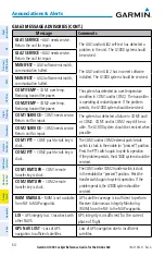
Page 79: ...anel self test has detected a problem in the unit Certain audio functions may still be avail able and the audio panel may still be usable The G1000 system should be serviced when possible GIA 63 Messa...

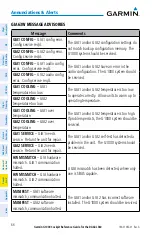
Page 80: ...OM1 needs service Return unit for repair The system has detected a failure in COM1 and or COM2 COM1 and or COM2 may still be us able The G1000 system should be serviced when possible COM2 SERVICE COM2...

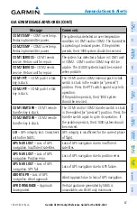
Page 81: ...nit for repair A failure has been detected in the GPS1 and or GPS2 receiver The receiver may still be available The G1000 system should be serviced GPS2 SERVICE GPS2 needs service Return unit for repa...

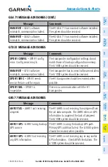
Page 82: ...ING GIA1 temperature too low The GIA1 and or GIA2 temperature is too low to operate correctly Allow units to warm up to operating temperature GIA2 COOLING GIA2 temperature too low GIA1 COOLING GIA1 ov...

Page 83: ...al push to talk switch is stuck in the enable or pressed position Press the PTT switch again to cycle its operation If the problem persists the G1000 system should be serviced COM2 PTT COM2 push to ta...

Page 84: ...service Return unit for repair NAV1 RMT XFR NAV1 remote transfer key is stuck The remote NAV1 and or NAV2 transfer switch is stuck in the enabled or pressed state Press the transfer switch again to cy...

Page 85: ...emory The G1000 system should be serviced MANIFEST GTX1 software mismatch communication halted The transponder has incorrect software installed The G1000 system should be serviced XPDR1 SRVC XPDR1 nee...

Page 86: ...date Update magnetic field model when practical GEO LIMITS AHRS1 too far North South no magnetic compass The aircraft is outside geographical limits for approved AHRS operation Heading is flagged as...

Page 87: ...re installed The G1000 system should be serviced Miscellaneous Message Advisories Message Comments FPL WPT LOCK Flight plan waypoint is locked Upon power up the G1000 system detects that a stored flig...

Page 88: ...e of airways in stored flight plans and reload airways as needed FPL TRUNC Flight plan has been truncated This occurs when a newly installed aviation database eliminates an obsolete approach or arriva...

Page 89: ...The system notifies the pilot to set the CDI to the correct NAV receiver Set the CDI to the correct NAV receiver PTK FAIL Parallel track unavailable bad geometry Bad parallel track geometry PTK FAIL P...

Page 90: ...WGS84 waypoint TRAFFIC FAIL Traffic device has failed The G1000 is no longer receiving data from the traffic system The traffic device should be serviced STRMSCP FAIL Stormscope has failed Stormscope...

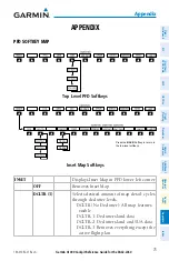
Page 91: ...Top Level PFD Softkeys ALERTS ADF DME Inset Map Softkeys Press the BACK Softkey to return to the top level softkeys STRMSCP ALERTS ALERTS ADF DME TRFC 1 TRFC 2 INSET Displays Inset Map in PFD lower l...

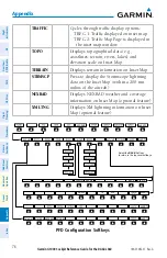
Page 92: ...data e g coastlines terrain rivers lakes and elevation scale on Inset Map TERRAIN Displays terrain information on Inset Map STRMSCP Press to display the Stormscope lightning data on the Inset Map wit...

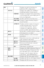
Page 93: ...TSIGNS Displays position markers for airports within approximately 15 nm of the current aircraft position Airport identifiers are displayed when the airport is within approximately 9 nm DFLTS Resets P...

Page 94: ...tting the altimeter and BARO settings to metric units METERS When enabled displays altimeter in meters IN Press to display the BARO setting as inches of mercury HPA Press to display the BARO setting a...

Page 95: ...Mode the transponder does not allow Mode A and Mode C replies but it does permit acquisition squitter and replies to discretely addressed Mode S interrogations VFR Automatically enters the VFR code 1...

Page 96: ...this level to return to the top softkey level STRMSCP NEXRAD XM LTNG optional optional optional AIRWAYS AIRWY LO AIRWAY HI AIRWY ON Default softkey is dependant on the selection made in the map setup...

Page 97: ...altitude airways are displayed STRMSCP Displays Stormscope weather and coverage information on Navigation Map optional feature NEXRAD Displays NEXRAD weather and coverage information on Navigation Ma...

Page 98: ...Guide for the DA42 L360 190 01062 01 Rev A Appendix 82 Flight Instruments EIS Nav Com XPDR Audio AFCS GPS Nav Flight Planning Procedures Hazard Avoidance Additional Features Abnormal Operation Annun A...

Page 99: ...Altitude Minimums 3 Barometric pressure 78 C CDI 1 10 73 Cell 35 36 Cell mode 36 Channel Presets 50 ChartView 46 47 Clearance player 11 Clearance Recorder 11 Code selection softkeys 9 COM 10 11 51 D D...

Page 100: ...bstacles 62 66 Overspeed Protection 14 P Pathways 45 46 R Reversionary mode 51 ROC 57 58 S SafeTaxi 46 SBAS 14 32 43 53 66 67 Store Flight Plan 27 Stormscope lightning data 35 36 76 Strike 35 Strike m...

Page 101: ......

Page 102: ...U S A p 503 391 3411 f 503 364 2138 Garmin Europe Ltd Liberty House Bulls Copse Road Hounsdown Business Park Southampton SO40 9RB U K p 44 0870 8501241 f 44 0870 8501251 Garmin Corporation No 68 Jangs...

Reviews: